Air input system, annular air duct and annular fluid bath of circular cooler

A technology of annular air duct and air inlet system, applied in the field of iron and steel smelting, can solve problems such as affecting the static sealing of the trolley and affecting the ventilation of the grate plate.

Active Publication Date: 2009-04-15
ZHONGYE-CHANGTIAN INT ENG CO LTD
View PDF0 Cites 13 Cited by
  • Summary
  • Abstract
  • Description
  • Claims
  • Application Information

AI Technical Summary

Problems solved by technology

[0006] see image 3 , is a radial sectional view of the annular air duct of the annular cooler 10, hot flue gas with a certain temperature passes through the annular air duct 33 from bottom to top, and the continuous passage of the hot flue gas will heat the annular air duct liquid tank of the annular water tank 34 The inner ring plate 341 and the outer ring plate 342 of the annular air channel liquid tank, the inner ring plate 341 of the annular air channel liquid tank is on the side closer to the center of the annular cooler 10 relative to the outer ring plate 342 of the annular air channel liquid tank, so that the inside of the annular water tank 34 When the liquid heats up, the liquid will vaporize when it reaches a certain temperature, and the vaporized liquid enters the trolley (not shown in the figure) along with the hot flue gas, so that the dust material sticks to the grate plate (not shown in the figure) of the trolley, affecting The ventilation of the grate plate will also cause the dust material on the lower plate of the trolley (not shown in the figure) to stick to the lower plate, affecting the static sealing of the trolley

Method used


Image

  • Air input system, annular air duct and annular fluid bath of circular cooler
  • Air input system, annular air duct and annular fluid bath of circular cooler
  • Air input system, annular air duct and annular fluid bath of circular cooler

Examples


Embodiment Construction

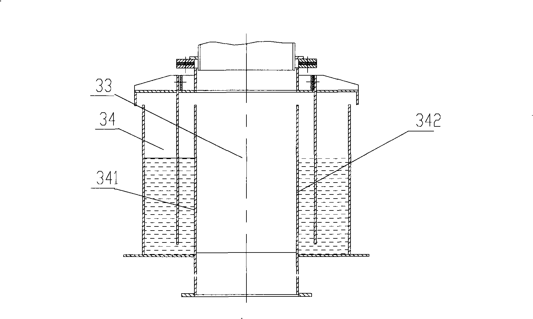
[0030] The invention improves the air intake system in the high temperature zone of the annular cooler, and sets the inner ring plate of the annular air duct liquid tank and the outer ring plate of the annular air duct liquid tank of the annular liquid tank in the air intake system as double-layer wall sleeves to avoid passing through the air duct The hot flue gas directly heats the liquid in the annular liquid tank, effectively preventing the liquid from heating up and vaporizing, which will affect the normal operation of other equipment of the annular cooler.

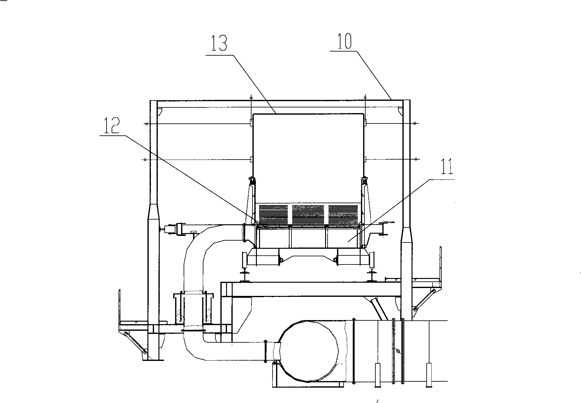
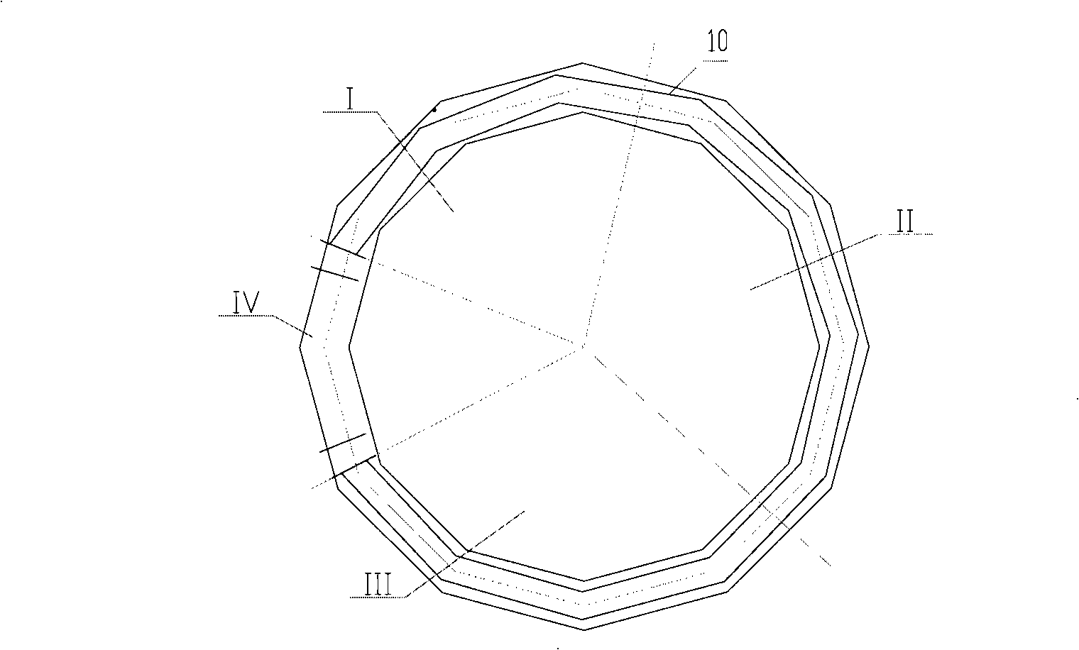
[0031] see Figure 4 , Figure 4 It is a radial cross-sectional view of the annular cooler 30 in the high temperature area. The annular air duct 31 is provided with a branch air duct 32 , and the branch air duct 32 is connected to the inlet of the annular air duct 33 . Each outlet of the annular air channel 33 is connected to each trolley air inlet pipe 36 respectively, and the trolley air inlet pipe 36 is fixed on t...


PUM


Abstract

The invention discloses a circular cooler air-feeding system, comprising an circular air pipe and a branch air pipe communicated with the circular air pipe; the branch air pipe is communicated with an circular air channel; the outlet of the circular air channel is communicated with a trolley air inlet pipe which is communicated with a trolley; the circular air channel consists of a circular liquid cell and a door-shaped sealing device; the door-shaped sealing device is connected with the trolley air inlet pipe; the circular liquid cell is covered by a sealing cover plate of the door-shaped sealing device; a door-shaped air-channel inner circular plate and a door-shaped air-channel outer circular plate of the door-shaped sealing device are extended downward to be below the liquid level of the circular liquid cell; the circular liquid cell consists of a circular air-channel liquid-groove inner circular plate, a circular air-channel liquid-groove outer circular plate, a liquid cell inner circular plate and a liquid cell outer circular plate; and the inner circular plate and outer circular plate of the circular air-channel liquid cell are all provided with the double-layer wall structure in the high-temperature zone of the circular cooler. The invention also discloses the circular air channel and the circular liquid cell of the circular cooler. The invention can prevent the liquid in the circular liquid cell from being gasified when the hot off-gas of the circular cooler is recycled so as to guarantee the normal work of the circular cooler.

Description

technical field [0001] The invention relates to the field of iron and steel smelting, in particular to an air inlet system, an annular air duct, and an annular liquid tank of an annular cooler. Background technique [0002] In iron and steel smelting, ring coolers are used to cool sintered materials. The ring cooler is in the shape of a ring as a whole, and the sintered material runs in the ring cooler for a week through a trolley to complete cooling and unloading. see figure 1 , is the radial (pointing to the center of the annular cooler) cross-sectional view of the annular cooler 10, the sintered material is laid on the grate plate 12 of the trolley 11, and the trolley 11 rotates at a constant speed around the center of the annular cooler 10. Simultaneously, the cold wind blown by blower (not shown in the figure) enters trolley through grate plate 12 from bottom to top, and after carrying out sufficient heat exchange with the material on grate plate 12, discharges from e...

Claims


Application Information

Patent Timeline
Patent Type & Authority Applications(China)
IPC IPC(8): F27D15/02
CPCF27D15/02
Inventor 高德亮
Owner ZHONGYE-CHANGTIAN INT ENG CO LTD
Why Eureka
Try Eureka