Automatic wall polishing facility

A kind of equipment and wall technology, which is applied in the field of automatic wall grinding equipment, can solve the problems of low automation degree, low grinding precision and quality, and unreasonable structural design of wall grinding equipment, so as to speed up grinding efficiency, liberate manpower, and ensure safety. The effect of operating distance

Pending Publication Date: 2019-04-19
QILU INST OF TECH
View PDF2 Cites 13 Cited by
  • Summary
  • Abstract
  • Description
  • Claims
  • Application Information

AI Technical Summary

Problems solved by technology

[0007] The purpose of the present invention is to propose an automatic wall grinding equipment to solve the problems of unreasonable structural design, low degree of automation, low grinding precision and quality in the prior art, so as to solve the above problems

Method used


Image

  • Automatic wall polishing facility
  • Automatic wall polishing facility
  • Automatic wall polishing facility

Examples


Embodiment 1

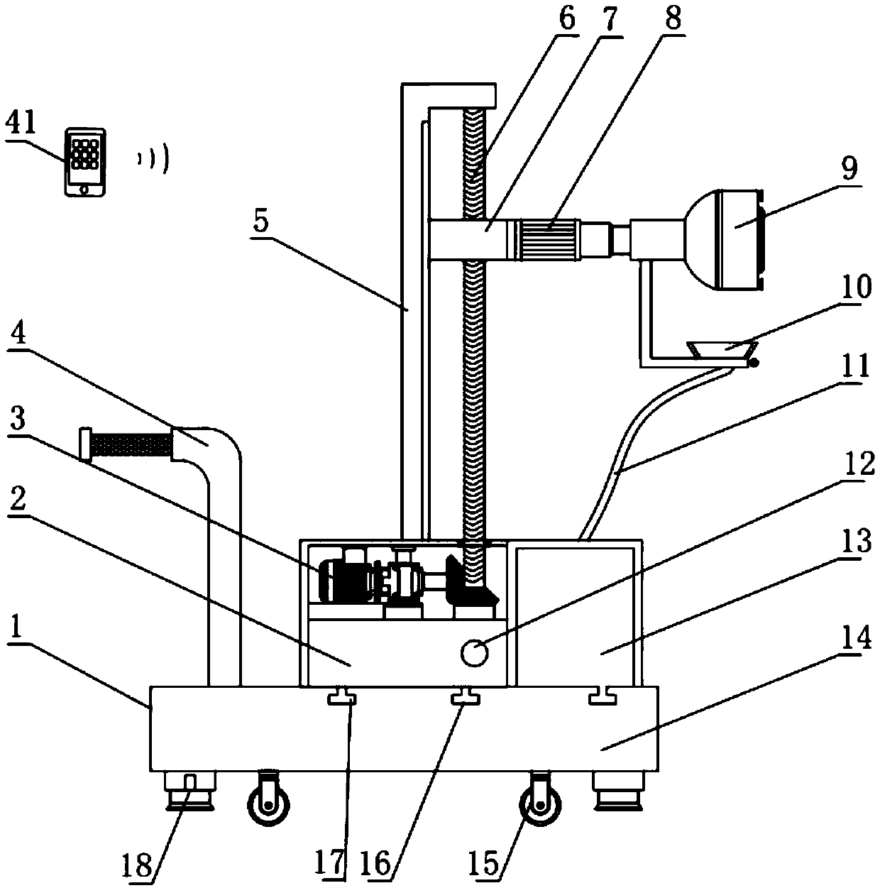
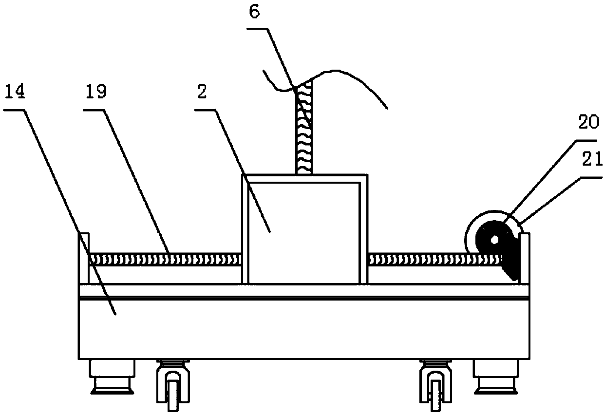
[0032] refer to Figure 1-2, a kind of automatic wall polishing equipment, comprises support and traveling mechanism 1 and polishing mechanism 9, and support and traveling mechanism 1 comprises a chassis 14, and the top surface of chassis 14 is provided with chassis 2, and first servomotor 3 is installed inside chassis 2 , and the output end of the first servo motor 3 is rotationally connected with the first threaded rod 6 through the bevel gear 20, the first threaded rod 6 is installed vertically on the top of the chassis 2, and the top surface of the chassis 2 is fixed on one side of the first threaded rod 6 L-shaped fixed plate 5, the surface of the first threaded rod 6 is connected with the grinding mechanism 9 through the adjustment block 7, the second threaded rod 19 is installed horizontally on the top surface of the chassis 14, and the second threaded rod 19 passes through the first threaded hole inside the chassis 2 12 is rotationally connected with the chassis 2, one...


PUM


Abstract

An automatic wall polishing facility comprises a supporting and travelling mechanism and a polishing mechanism. The supporting and travelling mechanism comprises a base plate. A machine box is arranged on the surface of the top of the base plate, and a first servo motor is installed inside the machine box. A bevel gear at one end is driven through rotation of the first servo motor, the bevel geardrives a first threaded rod to rotate, and therefore an adjusting block is connected with the first threaded rod in a rotating mode through a second threaded hole which is formed inside the adjustingblock, the adjusting block can slide up and down on the first threaded rod, and polishing of the portions, with different heights, of a wall is achieved. Meanwhile, a second threaded rod is horizontally installed on the top of the base plate, and drives a bevel gear to rotate through a second servo motor at one end of the second threaded rod, and therefore the machine box is connected with the second threaded rod in a rotating mode through a first threaded hole which is formed inside the machine box, and the machine box can move in the horizontal direction. Electric telescoping rods and buffersprings are installed on the side wall of the interior of the polishing mechanism so that buffering in the process that the facility makes contact with the wall can be provided. In addition, a dust absorption cover which is connected with an air blower is installed at the bottom end of the polishing mechanism so as to absorb the dust.

Description

technical field [0001] The invention relates to the technical field of civil engineering construction, in particular to an automatic wall grinding equipment. Background technique [0002] Wall grinding equipment is a commonly used operating equipment in civil construction and other fields. It is used to replace manpower to polish walls, protect the physical and mental health of workers, and improve the quality of construction or decoration. [0003] There are a lot of wall grinding equipment on the market now, and some of them save manpower to a certain extent, but there are still problems such as unreasonable structural design or low degree of automation, unreliable work, and limited grinding range. [0004] For example, the application number is 201811358963.3 Chinese invention patent discloses a hand-held dust-free building wall grinding device, including an installation box, a hand-held frame is fixed on the left end of the installation box, a grinding roller is installe...

Claims


Application Information

Patent Timeline
Patent Type & Authority Applications(China)
IPC IPC(8): B24B7/18B24B27/00B24B41/00B24B41/02B24B47/12B24B47/22B24B51/00B24B55/06
CPCB24B7/182B24B7/186B24B27/0007B24B41/00B24B41/02B24B47/12B24B47/22B24B51/00B24B55/06
Inventor 刘恩超叶知秋侯宇声
Owner QILU INST OF TECH
Why Eureka
Try Eureka