Grab bucket of continuous wall

A wall grab and grab technology, which is applied in the field of underground construction machinery, can solve the problems of unreachable, residual, low efficiency, etc., and achieve the effect of being easy to fall off and improving the grabbing efficiency.

Inactive Publication Date: 2016-08-17
JIANGSU ZISHI MACHINERY MFG
View PDF5 Cites 3 Cited by
  • Summary
  • Abstract
  • Description
  • Claims
  • Application Information

AI Technical Summary

Problems solved by technology

However, due to the uncertainty of the working medium, this goal has not been achieved
[0007] 3. During the unloading process of the bucket, only relying on the scraping action of the scraper and the impact between the grab body and the limit block to achieve the goal of fast and complete unloading of the working medium, the efficiency is low and there are often residues
[0008] The above three problems have seriously restricted the construction efficiency and service life of the diaphragm wall hydraulic grab

Method used


Image

  • Grab bucket of continuous wall
  • Grab bucket of continuous wall
  • Grab bucket of continuous wall

Examples


Embodiment Construction

[0030] The technical solutions of the present invention will be described in further detail below with reference to the accompanying drawings and embodiments.

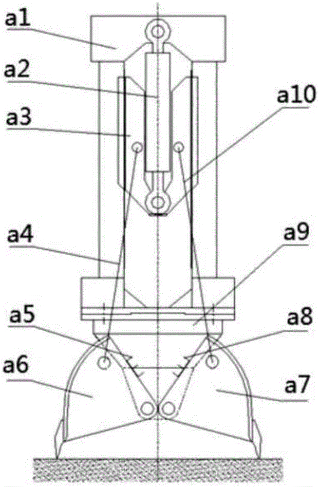
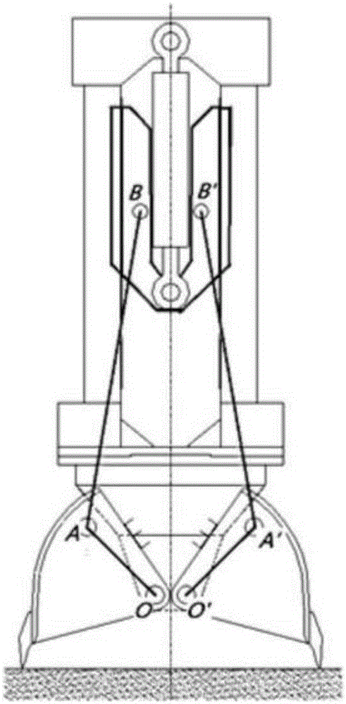
[0031] In order to facilitate the description of the solution to the existing problems of the existing diaphragm wall hydraulic grab, the structure of the existing diaphragm wall hydraulic grab is analyzed first. Such as figure 1 Shown is the structural schematic diagram of the existing diaphragm wall hydraulic grab. It can be seen from the figure that the slider a3 driven by the hydraulic cylinder a2 moves in the vertical direction, and the grab body a6, a7 is driven to rotate relative to the support a9 through the connecting rod a4, a10. The slider a3, the connecting rod a4, a10 and the grab body a6, 7 together form an equivalent slider crank mechanism, such as figure 2 shown. The vertical movement of B and B' makes A and A' rotate around 0 and 0' respectively to realize the opening and closing of the grab body. ...


PUM


Abstract

The invention relates to a grab bucket of a continuous wall. The grab bucket of the continuous wall comprises a machine body, a sliding mechanism, a grab bucket support and a grab bucket body. The sliding mechanism is arranged in the internal space of the machine body and can slide in the vertical direction relative to the machine body. The grab bucket body is hinged to the grab bucket support and connected with the sliding mechanism through a connection rod. The grab bucket body, the sliding mechanism and the connection rod form a crank-sliding block mechanism. An elastic device is arranged between the machine body and the grab bucket support, and the machine body, the elastic device and the grab bucket support form a micro-amplitude elastic vibration system jointly, so that the grab bucket body makes micro-amplitude swinging during construction of the grab bucket of the continuous wall. By means of the grab bucket of the continuous wall, the construction efficiency of the underground continuous wall project can be improved, and the service life of the underground continuous wall can be prolonged.

Description

technical field [0001] The invention relates to the field of underground construction machinery, in particular to a continuous wall grab. Background technique [0002] The mechanism structure of the diaphragm wall hydraulic grab can be attributed to a typical crank-slider mechanism. During operation, the system uses the hydraulic system to push the slider to slide up and down, and finally realizes the "crank mechanism" (grab body) through the force transmission of the connecting rod. ) swing, that is, the opening and closing of the grab body to complete the grabbing operation of the system. According to the different functions of the opening and closing of the grab body, the entire grab operation process can be divided into three stages: the self-weight falling stage, the hydraulic bucket closing stage, and the bucket opening and unloading stage. [0003] In the self-weight falling stage, a pair of grab bodies open to the maximum angle under the action of the hydraulic syst...

Claims


Application Information

Patent Timeline
Patent Type & Authority Applications(China)
IPC IPC(8): E02F5/02E02F3/60
CPCE02F5/025E02F3/60
Inventor 李华广
Owner JIANGSU ZISHI MACHINERY MFG
Why Eureka
Try Eureka