
A rapid air intake system for the lifting cylinder of the impact test bench

An air intake system, lift cylinder technology, applied in mechanical equipment, fluid pressure actuation devices, etc., can solve problems such as unreliable locking and unreliable locking of piston rods

Active Publication Date: 2018-07-27
SUZHOU FNS VIBRATION SYST
View PDF6 Cites 0 Cited by
  • Summary
  • Abstract
  • Description
  • Claims
  • Application Information

AI Technical Summary

Problems solved by technology

Since the hydraulic locking force of the hydraulic locking rod mechanism is limited, the smaller the diameter of the piston rod, the more reliable the locking, and the larger the diameter of the piston rod, the less reliable the locking. Therefore, the existing impact test bench The impact table can only be made into a small size. If the impact table of the impact test bench is made into a large size, the diameter of the piston rod of the lifting cylinder must be increased accordingly. Under the dual action, the hydraulic locking rod mechanism cannot reliably lock the piston rod

Method used


Image

  • A rapid air intake system for the lifting cylinder of the impact test bench
  • A rapid air intake system for the lifting cylinder of the impact test bench

Examples


Embodiment 1

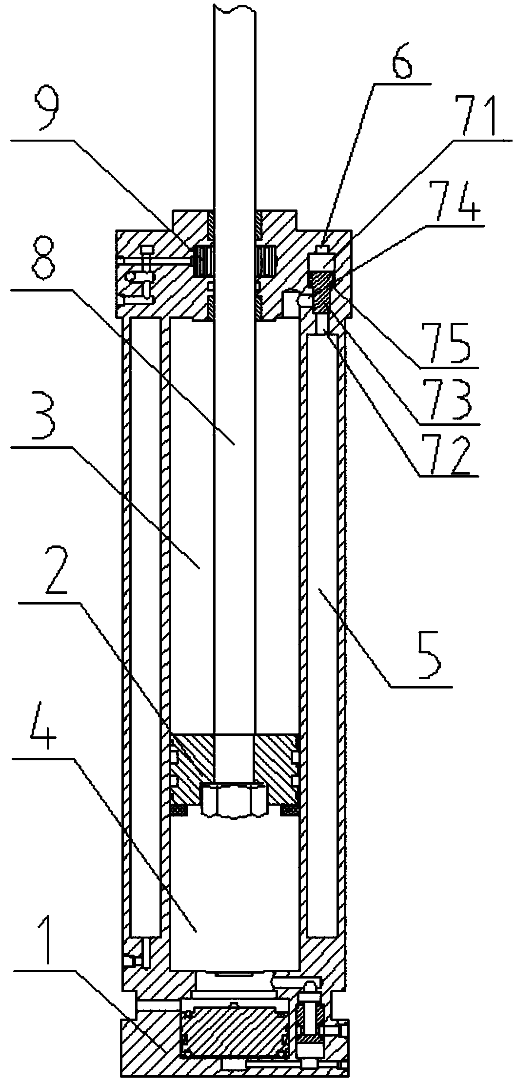
[0018] see figure 1 , as shown in the legend, a rapid air intake system for the lifting cylinder of an impact test bench. The lifting cylinder includes a cylinder body 1 and a piston 2. The cylinder body 1 is provided with a working chamber, and the piston 2 is dynamically sealed and slides up and down to connect the above working The side wall of the chamber divides the above-mentioned working chamber into a positive working chamber 3 located above and a reverse working chamber 4 located below. The above-mentioned rapid air intake system includes an annular air storage chamber 5 arranged outside the above-mentioned working chamber, The annular air distribution channel 6 arranged on the upper side of the above-mentioned working chamber and 7 air intake assemblies uniformly distributed along the horizontal ring direction, each air intake assembly includes a ventilation control chamber, a dynamic sealing sliding connection with the side wall of the ventilation control chamber An...

Embodiment 2

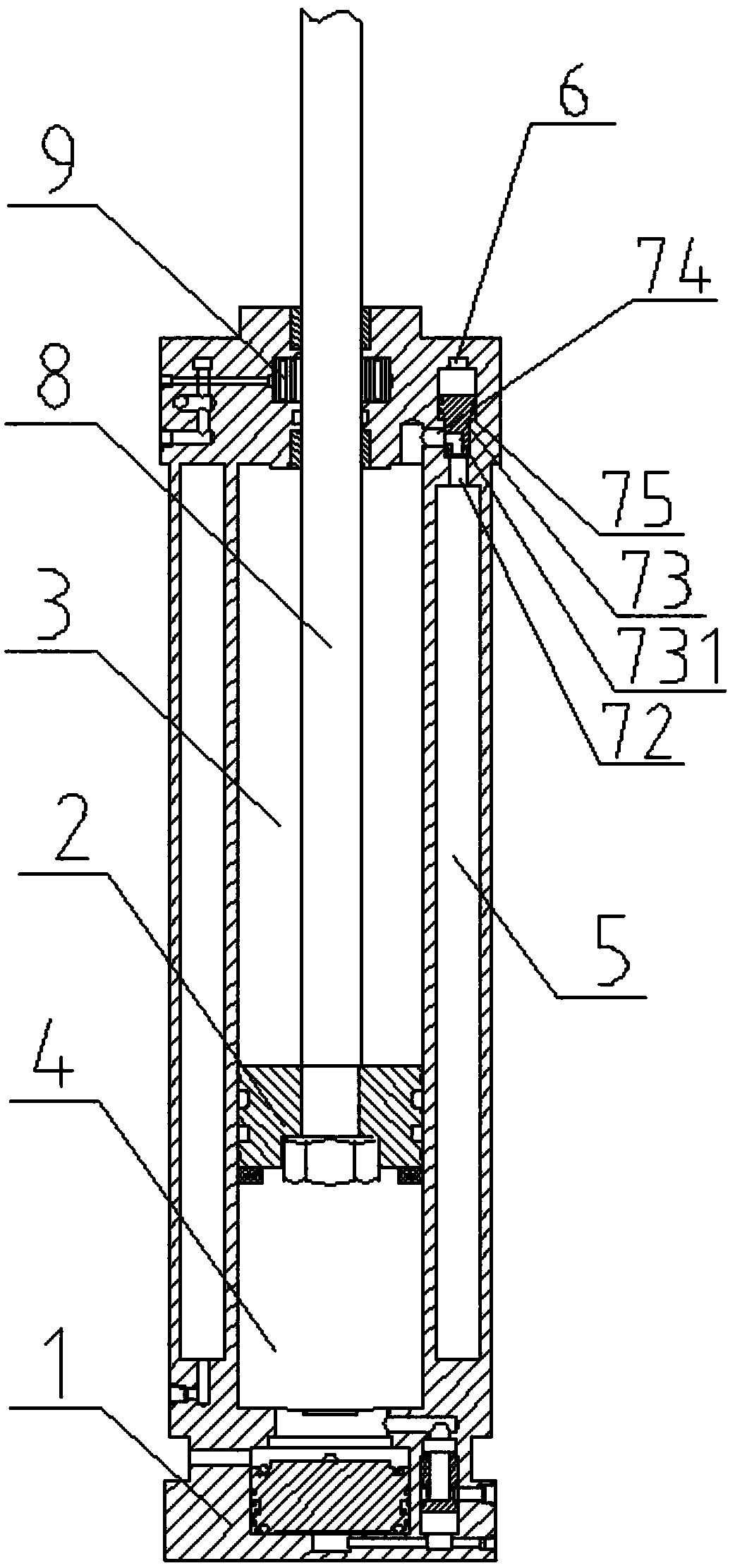
[0033] see figure 2 , as shown in the legend, the rest are the same as the first embodiment, the difference is that the sealing plug 73 is also provided with a vent channel 731, and the vent channel 731 communicates with the side wall of the vent chamber 72 and the sealing plug 73, and the vent port 74 is connected to the vent port 73. The channel 731 communicates or is blocked by the solid part of the sealing plug 73 .

[0034] When the positive working chamber 3 is not ventilated, the air in the control chamber 71 is discharged, and when the air pressure in the ventilation chamber 72 is less than the air pressure in the control chamber 71 to the set value, the sealing plug 73 moves to block the solid part of the sealing plug 73 Live the position of the ventilation port 74;

[0035] When ventilating to the working chamber 3, the air distribution channel 6 feeds the control air source into the control chamber 71, and when the air pressure in the control chamber 71 is greater...

Embodiment 3

[0037] The rest is the same as the first embodiment, except that the above-mentioned forward working chamber is a rodless chamber, and the above-mentioned reverse working chamber is a rod-bearing chamber.


PUM


Abstract

The invention discloses a fast air inlet system for a lifting air cylinder of a shock test table. The lifting air cylinder comprises a cylinder body and a piston, and the piston is connected to a side wall of a working chamber in a dynamic sealing and vertical sliding mode. The fast air inlet system comprises an air storage chamber, an air distribution channel and a plurality of air inlet assemblies; each air inlet assembly comprises a ventilation control chamber, a sealing plug connected to the ventilation control chamber in a dynamic sealing and sliding mode and a ventilation port formed in the side wall of the ventilation control chamber. When the fast air inlet system carries out shock tests, air does not need to be guided into a forward working chamber before the shock tests and just needs to be fast sucked when a hydraulic lock rod mechanism unlocks a piston rod, and therefore the hydraulic lock rod mechanism just receives the self weight load of a shock table board when locking the piston rod, the specification of the shock table board can be larger, and the large-diameter piston rod can be reliably locked by the hydraulic lock rod mechanism even if the diameter of the piston rod is increased.

Description

technical field [0001] The invention relates to the field of physical testing, in particular to a rapid air intake system for a lifting cylinder of an impact test bench. Background technique [0002] The acceleration impact testing machine is used to detect the ability of the product to withstand impact damage during transportation or use, so as to evaluate the impact resistance of the product structure, and through the test data, optimize the product structure strength and improve product quality. When the impact table of the impact table When it rises to a certain height, it will fall and hit the buffer pad, generating a semi-sine-shaped impact pulse. The impact test bench in the prior art includes an impact main body, an impact table above the impact main body, a lifting cylinder installed on the impact main body and drivingly connected to the impact table, and a hydraulic hydraulic locking rod mechanism that is locked and connected with the piston rod of the lifting cyli...

Claims


Application Information

Patent Timeline
Patent Type & Authority Patents(China)
IPC IPC(8): F15B15/14F15B15/20
CPCF15B15/1423F15B2215/30
Inventor 吕兴东宋雪芹许坚
Owner SUZHOU FNS VIBRATION SYST
Learn More