Pseudo base station detection system based on street lamp Internet of Things

A detection system and pseudo base station technology, applied in the field of smart cities, can solve the problems that it is difficult to realize the whole network, all-day, real-time test, the tracking and positioning of pseudo base stations, and the inability to achieve large-scale coverage.

Active Publication Date: 2016-08-17
东莞中科智城软件有限公司
View PDF5 Cites 14 Cited by
  • Summary
  • Abstract
  • Description
  • Claims
  • Application Information

AI Technical Summary

Problems solved by technology

[0005] 1. The cost of road testing is high and the manpower is limited. It is difficult to realize the whole network, all-day, real-time testing. It can only be carried out in key areas or after user complaints occur;
[0006] 2. As the new pseudo base stations tend to be more and more miniaturized and mobile, many pseudo base stations are installed on the car, and the effective and large-scale coverage of the detection cannot be achieved by using the road test method. , the mobile terminal can only restore the network when it leaves the signal area of ​​the pseudo base station, and there will be a certain information delay;
[0007] 3. Neither of the above two methods can realize the tracking and positioning of the real-time trajectory of the pseudo base station, nor can it realize the direct evidence collection of the criminal vehicle

Method used


Image

  • Pseudo base station detection system based on street lamp Internet of Things
  • Pseudo base station detection system based on street lamp Internet of Things
  • Pseudo base station detection system based on street lamp Internet of Things

Examples


Embodiment Construction

[0037] In order to make the above objects, features and advantages of the present invention more comprehensible, the technical solutions of the present invention will be described in detail below in conjunction with the accompanying drawings and specific embodiments. It should be pointed out that the described embodiments are only a part of the embodiments of the present invention, rather than all embodiments. Based on the embodiments of the present invention, all those skilled in the art can obtain without creative work. Other embodiments all belong to the protection scope of the present invention.

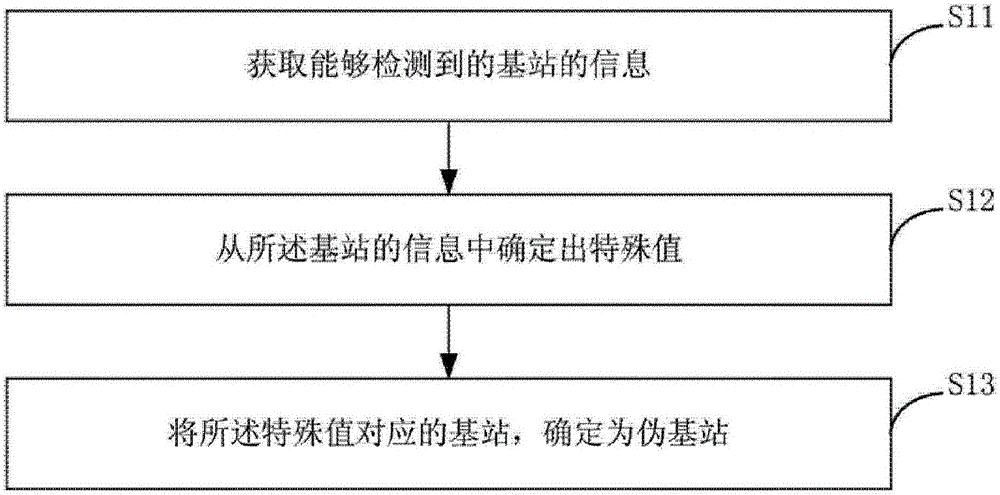
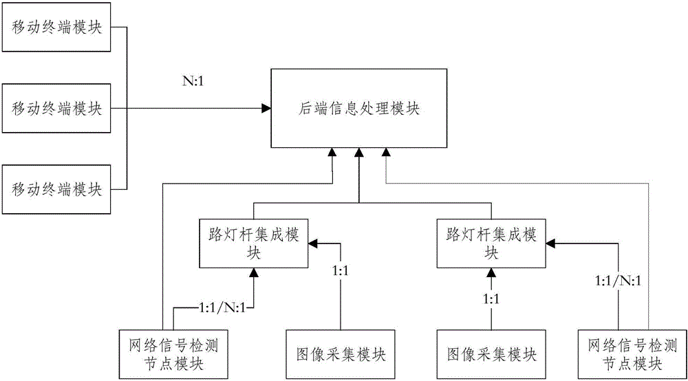
[0038] The present invention realizes the detection of pseudo-base station signals and rough positioning of pseudo-base stations through the detection of mobile terminal modules, combined with the information collected by the network signal detection node module and the street light pole integration module carried on the actual street light pole, the back-end information processin...


PUM


Abstract

The invention discloses a pseudo base station detection system based on a street lamp Internet of Things. The pseudo base station detection system comprises a rear end information processing module, a plurality of mobile terminal modules, a plurality of network signal detection node modules, a plurality of light pole integration modules and a plurality of image collecting modules. Through the detection of the mobile terminal modules, the detection of pseudo base station signals and coarse positioning of pseudo base stations are implemented; in combination with information collected by the network signal detection node modules and the light pole integration modules which are loaded on actual light poles, the rear end information processing module synthesizes information analysis of the mobile terminal modules, the network signal detection node modules and the light pole integration modules to perform accurate positioning and track analysis on the pseudo base stations, and the rear end information processing module records picture information of pseudo base station carriers collected by image collecting and processing units in the light pole integration modules and base station data information into an evidence collection information base.

Description

technical field [0001] The invention relates to the technical field of smart cities, in particular to a pseudo-base station detection system based on the Internet of Things of street lamps. Background technique [0002] The current GSM mobile communication system adopts a one-way authentication system, that is, only the network authenticates the terminal, and does not require the terminal to authenticate the network. "Illegal base station" (also known as "pseudo base station" or "simulation base station") equipment utilizes this loophole in the GSM system protocol. For the WCDMA mobile communication system that adopts two-way authentication, there is also a certain protocol loophole, so that the illegal base station can use this loophole to obtain the IMSI and IMEI information of the WCDMA mobile terminal before the terminal authenticates the network, and then carry out similar information attacks. . [0003] At present, detection and positioning of pseudo base stations ma...

Claims


Application Information

Patent Timeline
Patent Type & Authority Applications(China)
IPC IPC(8): H04W4/02H04W12/12H04W24/08H04W64/00H04N7/18G08G1/01G08G1/017H04W12/122
CPCH04N7/181H04W4/025H04W12/12H04W24/08H04W64/00G08G1/0116G08G1/0137G08G1/0175
Inventor 袁峰李引陈升东
Owner 东莞中科智城软件有限公司
Why Eureka
Try Eureka