
Biomass gasifying machine

A biomass and gasification agent technology, applied in the manufacture of combustible gas, petroleum industry, etc., can solve the problems of no practicality and promotion value, poor continuity and stability, and insufficient fuel burnout, etc., to achieve simple structure, work Stable and continuous effect with long gas production time

Inactive Publication Date: 2016-08-24
CHONGQING DINGSHENG BIOTECH CO LTD
View PDF0 Cites 0 Cited by
  • Summary
  • Abstract
  • Description
  • Claims
  • Application Information

AI Technical Summary

Problems solved by technology

[0002] The current so-called straw gasifiers or biomass gasifiers generally have some serious performance problems, such as: fire layer perforation, fire layer bridging and fire layer inclination will lead to qualitative changes in gasification products, resulting in non-combustible smoke, resulting in The gas production time is short, the continuity and stability are poor, the fuel cannot be fully burned, and the waste is large, making it unable to operate normally. The product is only an experimental phenomenon of gas generation due to thermal solution, which has no practicality and promotion value.

Method used


Image

  • Biomass gasifying machine
  • Biomass gasifying machine
  • Biomass gasifying machine

Examples


Embodiment Construction

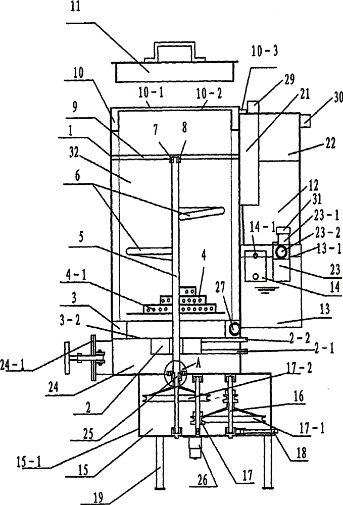
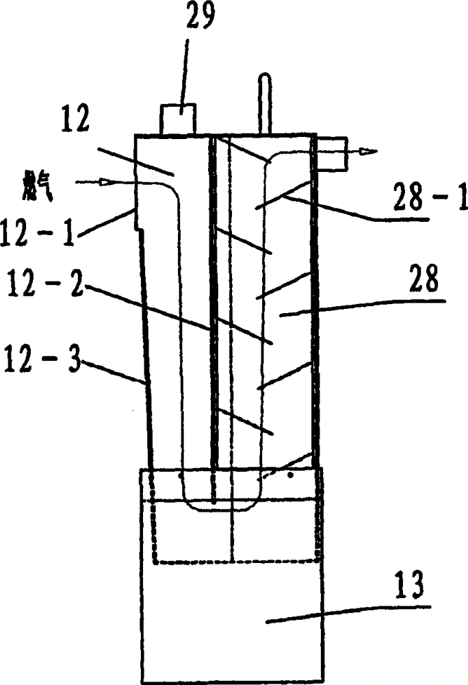
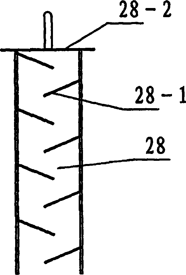
[0021] Such as Figures 1 to 5 As shown, a biomass gasifier includes a furnace body 1 with a furnace cover 11, wherein the annular gasification agent preheating chamber 3 at the lower end of the furnace body 1 divides its inner chamber into upper and lower chambers, namely The upper chamber is the furnace 32, the lower chamber is the ash chamber 24, the lower end of the furnace body 1 is provided with a gearbox 15, the gearbox 15 includes a casing 15-1 and a motor 26, and the motor 26 is inserted into the output shaft of the casing 15-1 for loading Belt pulley 17 is arranged, and this belt pulley 17 is connected with belt pulley 17-1 on the belt pulley rotating shaft 16, and belt pulley 17-1 on the belt pulley rotating shaft 16 is connected with belt pulley 17-2 on the center shaft 5, and belt tightness adjustment is also connected on the belt pulley rotating shaft 16 Rod 18, that is, the output shaft of the gearbox is the central axis 5 of the furnace body; the central axis 5...


PUM


Abstract

The invention discloses a biomass gasification machine and belongs to the technical field of a biomass gasification device. The biomass gasification machine comprises a furnace body with a furnace cover, wherein an inner chamber of the furnace body is divided into a furnace hearth and an ash chamber by an annular gasifying agent preheating chamber on the lower end of the furnace body; the lower end of the furnace body is provided with a gearbox; an output shaft of the gear box is a central shaft of the furnace body; the central shaft is connected with a furnace base plate through a dynamic sealing device; the upper end of the central shaft is fixedly connected with a bracket in the furnace hearth; an inner ring bracket of the gasifying agent preheating chamber is fixedly connected with a steam generator; the gasifying agent preheating chamber is communicated with a gas outlet pipe of the steam generator; the gasifying agent preheating chamber is communicated with a gasifying agent input pipe along the tangential direction; a plurality of jet nozzles are arranged on an inner ring of the gasifying agent preheating chamber; the central shaft is fixedly connected with an wind distribution furnace disc and a pressure stirring arm of an eccentric tower; and the upper end of the furnace body is provided with a fuel gas port. The biomass gasification machine has the advantages of long gas production time, stable and continuous operation, no flameout in midway, environmental protection, energy conservation, explosiveness prevention, and high thermal mass.

Description

technical field [0001] The invention relates to a gasification device, in particular to a crop straw or other biomass gasification device. Background technique [0002] The current so-called straw gasifiers or biomass gasifiers generally have some serious performance problems, such as: fire layer perforation, fire layer bridging and fire layer inclination will lead to qualitative changes in gasification products, resulting in non-combustible smoke, resulting in The gas production time is short, the continuity and stability are poor, the fuel cannot be fully burned, and the waste is large, making it unable to operate normally. Contents of the invention [0003] Based on the defects of the prior art, the purpose of the present invention is to: provide an automatic control fire layer change, long gas production time, fuel can be fully burned, stable and continuous work, not extinguishing halfway, and environmental protection, energy saving, explosion-proof and high heat High...

Claims


Application Information

Patent Timeline
Patent Type & Authority Applications(China)
IPC IPC(8): C10J3/20C10J3/84C10J3/72
Inventor 谢兵郑浩然
Owner CHONGQING DINGSHENG BIOTECH CO LTD
Learn More