Rare earth extracting and impurity removing device

An extraction and rare earth technology, which is applied in the field of rare earth extraction and impurity removal devices, can solve the problems that the impurity removal effect is easily affected by human factors, it is difficult to achieve the flow synchronization of separation and extraction tanks, and multi-process materials, etc., to achieve efficient and stable impurity removal effect. The effect of reducing backlog and continuous impurity removal

Active Publication Date: 2016-08-24
CHALCO GUANGXI RARE EARTH DEV CO LTD
View PDF3 Cites 6 Cited by
  • Summary
  • Abstract
  • Description
  • Claims
  • Application Information

AI Technical Summary

Problems solved by technology

[0003] Although this kind of equipment can satisfy the operation of the separation and extraction tank, it has the following disadvantages: 1. The impurity removal process is intermittent production, which requires many equipment, long steps, and a large backlog of process materials; 2. The extraction and removal process requires The impurity removal effect is easily affected by human factors; 3. After the impurity removal, the feed liquid can only be introduced into the separation extraction tank through the high level tank or the pump to control the flow rate, and it is difficult to synchronize the flow rate with the separation extraction tank

Method used


Image

  • Rare earth extracting and impurity removing device
  • Rare earth extracting and impurity removing device
  • Rare earth extracting and impurity removing device

Examples


Embodiment Construction

[0020] The technical solution of the present invention is further described below, but the scope of protection is not limited to the description.

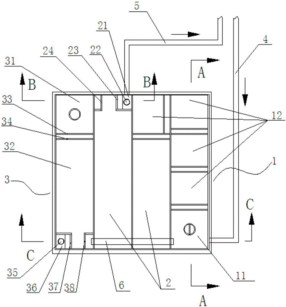
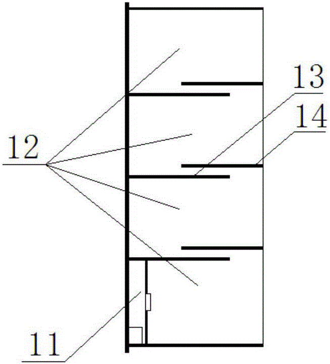
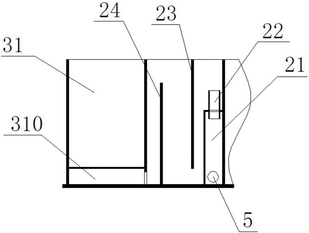
[0021] Such as Figure 1 ~ Figure 4 The rare earth extraction and impurity removal device shown includes an extraction impurity removal chamber 1 and a feed liquid clarification chamber 2, the latent chamber A11 of the extraction impurity removal chamber 1 communicates with the feed liquid introduction pipe 4, and the water in the feed liquid clarification chamber 2 The phase chamber A21 communicates with the feed liquid outlet pipe 5; the extraction impurity removal chamber 1 is provided with a submerged chamber A11 and a plurality of mixing chambers A12, and each mixing chamber A12 is separated by an overflow plate A13 and a baffle plate A14, The overflow plate A13 is fixed on the bottom of the extraction impurity removal chamber 1 and its height is lower than the depth of the extraction impurity removal chamber 1, and the baffle...


PUM


Abstract

The invention provides a rare earth extracting and impurity removing device. A hidden chamber A of an extracting and impurity removing chamber is communicated with a feed liquid guide-in pipe. A water phase chamber A of a feed liquid clarifying chamber is communicated with the feed liquid guide-out pipe. The hidden chamber A and multiple mixing chambers A are arranged in the extracting and impurity removing chamber. The mixing chambers are partitioned through overflowing plates A and flow blocking plates A. The overflowing plates A are fixed to the bottom of the extracting and impurity removing chamber, and the height of the overflowing plates A is smaller than the depth of the extracting and impurity removing chamber. The flow blocking plates A are fixed to the upper portion of the extracting and impurity removing chamber, and the lower ends of the flow blocking plates do not make contact with the bottom of the extracting and impurity removing chamber. After the device is adopted for removing impurities, continuous production process is achieved in the extracting and impurity removing processes, the impurity removing and extracting agent can be recycled automatically, and material overstock is reduced; no staff are needed for carrying out operation, and the impurity removing effect is efficient and stable; feed liquid automatically flows back to a separating and extracting groove after the impurities are removed, and the speed of the feed liquid is synchronous with the flowing speed of the separating and extracting groove.

Description

technical field [0001] The invention relates to the technical field of rare earth extraction and separation, in particular to a rare earth extraction and impurity removal device. Background technique [0002] In the extraction and separation process of rare earth, part of the aqueous phase feed liquid contains relatively high content of non-rare earth impurities such as iron and lead, especially in the stripping liquid. These feed liquids containing non-rare earth impurities will cause the emulsification of the extractant and the increase of three-phase matter, which will affect the effect of extraction and separation. Therefore, in production, it is necessary to draw this part of feed liquid from the rare earth separation and extraction tank, remove the non-rare earth impurities therein and then return to the separation and extraction tank. The existing impurity removal equipment is a single-stage extraction and impurity removal reaction kettle. First, the impurity removal...

Claims


Application Information

Patent Timeline
Patent Type & Authority Applications(China)
IPC IPC(8): C22B3/02C22B3/22C22B59/00
CPCC22B3/02C22B3/22C22B59/00Y02P10/20
Inventor 马朝扬甘家毅李容军陶理科熊吉磊乔自强
Owner CHALCO GUANGXI RARE EARTH DEV CO LTD
Why Eureka
Try Eureka