Impact device and control terminal

A technology for controlling terminals and percussion devices, which is applied in the direction of instruments, analysis materials, ultrasonic/sonic/infrasonic generation, etc., which can solve the problems of heavy workload, cumbersome process, and long detection time of detection personnel, and achieve shortened detection time and improved Detection efficiency, the effect of simplifying the detection process

Active Publication Date: 2016-08-24
ZHANJIANG JIANKE ENG QUALITY TESTING CENT CO LTD
View PDF6 Cites 1 Cited by
  • Summary
  • Abstract
  • Description
  • Claims
  • Application Information

AI Technical Summary

Problems solved by technology

[0005] The technical problem to be solved by the present invention is to overcome the shortcomings of the inconvenient movement of the standard striker in the prior art, which leads to heavy workload, cumbersome process, long detection time and low on-site detection efficiency.

Method used


Image

  • Impact device and control terminal
  • Impact device and control terminal
  • Impact device and control terminal

Examples


Embodiment 1

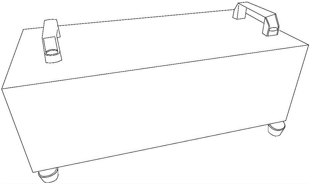
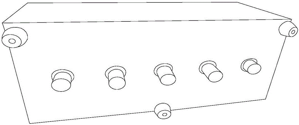
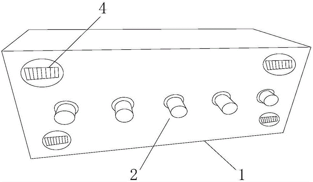
[0037] This embodiment provides a striker, such as Figure 3A As shown, it includes chassis 1, hammer 2 and power connection terminal. The power connection end is used to connect to a power supply, and one end of the cable can be connected to the power connection end and the other end can be connected to an AC power socket, or the power connection end can be connected to a battery. Striking hammer 2 is positioned at the bottom of cabinet 1, is used for hitting ground. Inside the cabinet 1 there is a first driving device 3 for driving the hammer 2 to hit the ground. The power connection terminal is connected with a power source and supplies power to the first driving device 3 .

[0038] The striker also includes a walking device 4, a second driving device 5, a first wireless communication unit 6 and a main controller 7, such as Figure 3B shown.

[0039] The running device 4 is located at the bottom of the chassis 1 and is used to drive the chassis 1 to walk.

[0040] The se...

Embodiment 2

[0050] This embodiment provides a control terminal, such as Figure 4A As shown, it includes a striker control interface 41 and a second wireless communication unit 42 .

[0051] The percussion device control interface 41 is used for receiving the control command of the percussion device described in Embodiment 1. When the inspector operates the control terminal to control the percussion device, the control command is input through the percussion device control interface.

[0052] The second wireless communication unit 42 is connected to the percussion device control interface, and is used for transmitting control commands to the percussion device.

[0053] The above-mentioned control terminal receives the control command of the striker through the striker control interface; transmits the control command to the striker through the second wireless communication unit. Using the control terminal, the inspector can conveniently control the walk of the striker.

[0054] As a pref...


PUM


Abstract

The invention discloses an impact device and a control terminal. The impact device comprises a case, an impact hammer and a power connecting end. The impact hammer is located at the bottom of the case and used for impacting on the ground, and a first driving device for driving the impact hammer to impact on the ground is arranged in the case. The impact device further comprises a walking device, a second driving device, a first wireless communication unit and a main controller, wherein the walking device is located at the bottom of the case and used for driving the case to walk; the second driving device is powered by the power connecting end and connected with the walking device and used for driving the walking device to walk in a predetermined direction at a predetermined rate; the first wireless communication unit is used for receiving a control command of the control terminal; the main controller is used for controlling the first driving device to drive the impact hammer to impact the ground and/or controlling the second driving device to drive the walking device to walk according to the control command. A detector can control the movement position of the impact device without climbing to a room on the upper layer, so that the detection process is simplified, the workload of the detector is reduced, detection time is shortened, and on-site detection efficiency is improved.

Description

technical field [0001] The invention relates to the field of architectural acoustic detection, in particular to a striker and a control terminal. Background technique [0002] The on-site inspection of building acoustics is an important task in the process of promoting green buildings, and the on-site inspection of floor impact sound insulation performance is one of the important inspection items in the inspection of building sound insulation performance. The test is mainly based on "Acoustic Building and Building Component Sound Insulation Measurement Part 7: On-site Measurement of Floor Impact Sound Insulation" (GB / T 19889.7-2005) and "Building Sound Insulation Evaluation Standard" (GB / T50121-2005). During the detection, the impactor is used to hit the floor, and at the same time, the impact sound pressure level is measured with a microphone on the floor below the floor. The detection process requires the striker to hit at least four different positions on the floor. The ...

Claims


Application Information

Patent Timeline
Patent Type & Authority Applications(China)
IPC IPC(8): G01N29/34
CPCG01N29/34G01N2291/023
Inventor 华实周冬林
Owner ZHANJIANG JIANKE ENG QUALITY TESTING CENT CO LTD
Why Eureka
Try Eureka