Fluorescent lamp test frame with flat cable grooves

A technology of fluorescent lamps and test racks, which is applied in the direction of the measuring device casing, etc., can solve the problems of confusing wire connections, restless workers, and low work efficiency, and achieves the effects of convenient operation, large up and down space, and improved work efficiency

Inactive Publication Date: 2016-08-24
PINGHU IENERGY LIGHTING CO LTD
View PDF6 Cites 5 Cited by
  • Summary
  • Abstract
  • Description
  • Claims
  • Application Information

AI Technical Summary

Problems solved by technology

When fluorescent lamps leave the factory, necessary aging and testing experiments are required to ensure the performance of the product, but different specifications often require different aging racks to complete, which undoubtedly brings inconvenience to the manufacturer
In order to increase the number of LED fluorescent lamps installed in the existing fluorescent lamp test stand, as many lamp holders as possible are installed on the test stand. Once the number of lamp holders is large, the number of wires will increase. If there are too many wires, the connection of the wires will be confused. Hanging the wires outside the lamp holder is easy to touch when installing and disassembling the fluorescent tube, which is inconvenient to operate, and there is no cooling device on the test stand. Working in the hot summer will easily cause the workers to feel irritable and the work efficiency will be low

Method used


Image

  • Fluorescent lamp test frame with flat cable grooves
  • Fluorescent lamp test frame with flat cable grooves
  • Fluorescent lamp test frame with flat cable grooves

Examples


Embodiment Construction

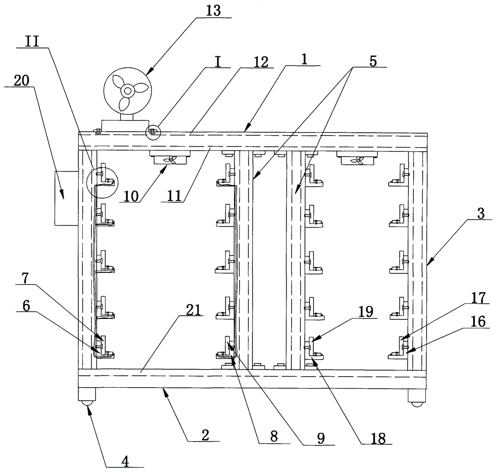
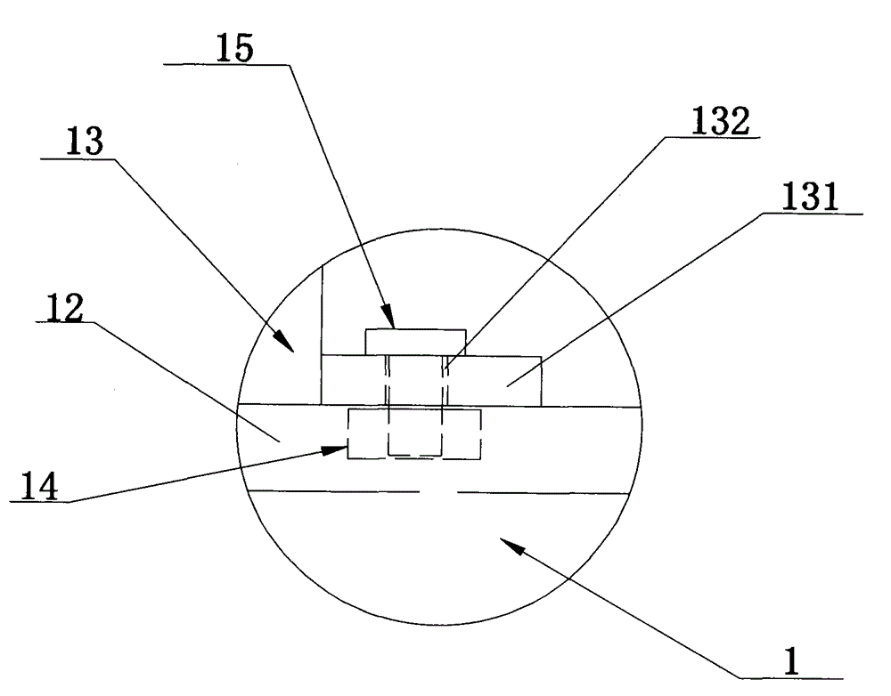
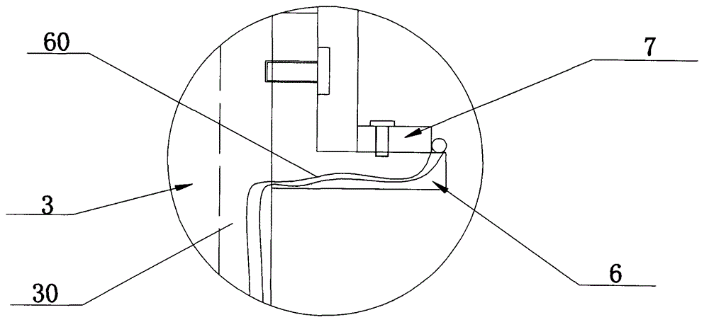
[0017] see figure 1 , figure 2 , image 3 and Figure 4 , the present invention discloses a fluorescent lamp test frame with a wiring trough, which includes a bracket, which is a rectangular body constructed of profiles, including an upper rectangular frame 1, a lower rectangular frame 2, and four fixed columns 3. The lower rectangular frame A pulley 4 is installed at the bottom of the frame 2, an upper groove rail 11 is provided in the middle of the lower end faces of the two long sides of the upper rectangular frame 1, and a lower groove rail 21 is arranged in the middle of the upper end faces of the two long sides of the lower rectangular frame 2. Four sliding uprights 5 are arranged between the rail 11 and the lower grooved rail 21, and several first angle steels 6 are evenly arranged between the two fixed uprights 3 at the left end of the lower rectangular frame 2 from bottom to top, each first Several first lamp holders 7 are detachably arranged on the angle steel 6,...


PUM


Abstract

The invention discloses a fluorescent lamp test frame with flat cable grooves. The fluorescent lamp test frame comprises a bracket. The bracket comprises an upper rectangular frame, a lower rectangular frame and four fixed vertical columns, wherein the upper rectangular frame, the lower rectangular frame and the four fixed columns are connected; the upper rectangular frame is detachably provided with a first radiating fan, the upper end of the upper rectangular frame is provided with a second radiating fan, the upper end face of the upper rectangular frame is provided with a fan adjusting groove, the fan adjusting groove is internally provided with a positioning sliding block, the lower end of the radiating fan is integrally provided with two positioning convex blocks, the middle part of each positioning convex block is provided with a connecting hole, the connecting hole is internally provided with a bolt in a run-through manner, and the radiating fan is fixedly connected with the positioning slide block through the bolts; each fixed vertical column is vertically provided with a first flat cable groove, each sliding vertical column is vertically provided with a second flat cable groove, both the first flat cable grooves and the second flat cable grooves are internally provided with connecting wires, and the sections, which extend out of the flat cable grooves, of the connecting wires are placed on the upper end face of aligned angle steel. According to the technical scheme, the fluorescent lamp test frame has the advantages of reasonable wire installation, convenient operation and ability of improving the work efficiency.

Description

technical field [0001] The invention relates to the technical field of electrical equipment, in particular to a fluorescent lamp test frame with a wiring groove. Background technique [0002] LED fluorescent lamps are the mainstream energy-saving lighting products at present, and they have various specifications and are used in a wide range of occasions. When fluorescent lamps leave the factory, necessary aging and testing experiments are required to ensure the performance of the product. However, different specifications often require different aging racks to complete, which undoubtedly brings inconvenience to the manufacturer. In order to increase the number of LED fluorescent lamps installed in the existing fluorescent lamp test stand, as many lamp holders as possible are installed on the test stand. Once the number of lamp holders is large, the number of wires will increase. If there are too many wires, the connection of the wires will be confused. Hanging the lead wire...

Claims


Application Information

Patent Timeline
IPC IPC(8): G01R1/04
Inventor 姜高严佳健俞申玮
Owner PINGHU IENERGY LIGHTING CO LTD
Why Eureka
Try Eureka