
An active optical cable connector with a switchable interface, a method for using the same, and a method for manufacturing an optical cable

An optical cable connector and optical cable technology, which is applied in the field of optical cable manufacturing and active optical cable connectors, can solve the problems of optical fiber damage, large optical signal loss, and high requirements on the bending resistance of optical cables, so as to achieve ease of use, high transmission quality and high reliability. Transfer rate, practical effect

Active Publication Date: 2018-09-07
深圳市鑫明康精密电子有限公司
View PDF7 Cites 0 Cited by
  • Summary
  • Abstract
  • Description
  • Claims
  • Application Information

AI Technical Summary

Problems solved by technology

[0005] However, the current existing active optical cables have the following deficiencies: ①Because the currently commonly used data interfaces include USB interface and HDMI interface, most active optical cables are currently only designed for USB interfaces, and their two ends are fixed interfaces, When changing data interfaces of different specifications, users need to use different active optical cables, such as 4-PIN USB interface, 5-PIN USB interface, 8-PIN USB interface, 10-PIN USB interface, 8-PIN-2* 4. The conversion problem between various USB interfaces such as USB interface and Micro USB interface, and even the conversion problem between USB interface and HDMI interface
②Because of the environment in which the active optical cable is used, the bending resistance of the optical cable is highly required. When using the active optical cable, the user will often curl and bend the active optical cable. Prone to large optical signal loss, fiber damage and other problems

Method used


Image

  • An active optical cable connector with a switchable interface, a method for using the same, and a method for manufacturing an optical cable
  • An active optical cable connector with a switchable interface, a method for using the same, and a method for manufacturing an optical cable
  • An active optical cable connector with a switchable interface, a method for using the same, and a method for manufacturing an optical cable

Examples


Embodiment Construction

[0043] All features disclosed in this specification, or steps in all methods or processes disclosed, may be combined in any manner, except for mutually exclusive features and / or steps.

[0044] Any feature disclosed in this specification (including any appended claims, abstract), unless otherwise stated, may be replaced by alternative features which are equivalent or serve a similar purpose. That is, unless expressly stated otherwise, each feature is one example only of a series of equivalent or similar features.

[0045] (1) Active Optical Cable Connector

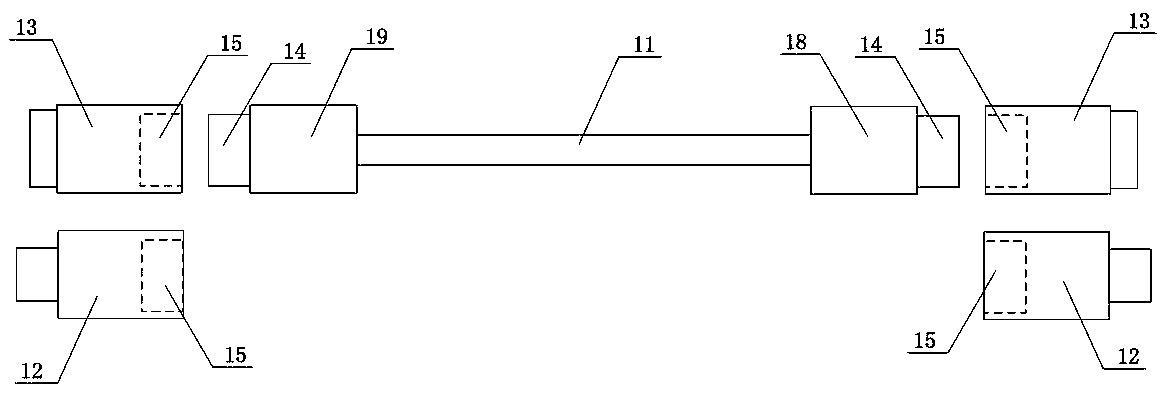
[0046] Such as figure 1 as shown, figure 1 An active optical cable connector with a switchable interface is described, and the active optical cable connector includes: an optical cable body 11 , a USB interface module 12 and an HDMI interface module 13 .

[0047] The first end of the optical cable body 11 is fixedly provided with a first photoelectric conversion module 18, and its second end is fixedly provided with a s...


PUM


Abstract

The invention discloses an active optical cable connector with a switchable interface, and an application method of the active optical cable connector. The active optical cable connector can realize the facts that USB signals or HDMI signals are converted into optical signals, and single transmission is performed through an optical fiber; a first photoelectric conversion module (18) is fixedly arranged at one end of an optical cable body (1); the first photoelectric conversion module (18) is connected with a USB interface module (12) or an HDMI interface module (13) in a pluggable way through a first connector (14) and a second connector (15) which are matched with each other, so as to form a switchable optical cable end interface (16). The active optical cable connector abandons the traditional cable signal transmission mode, and has higher transmission quality and transmission speed. The invention further provides a manufacture method of an optical cable, and ensures that the optical cable adopted by the active optical cable connector has a higher bending characteristic and practicability, and is convenient to use, store and curl.

Description

technical field [0001] The invention relates to the field of optical fiber technology, in particular to an active optical cable connector with a switchable interface, a method for using the same, and a method for manufacturing an optical cable. Background technique [0002] In the era of big data, there are more and more high-density and high-bandwidth applications. At this time, passive optical cables or copper-based cable systems are stretched. In order to ensure the stability of transmission and flexible applicability, users urgently need a new type of product as the main transmission medium for high-performance computing and data centers. In this case, active optical cable products emerge as the times require. [0003] Active optical cable refers to a communication cable that needs to use external energy to convert electrical signals into optical signals or convert optical signals into electrical signals during the communication process. The optical transceivers at both ...

Claims


Application Information

Patent Timeline
Patent Type & Authority Patents(China)
IPC IPC(8): G02B6/42G02B6/036G02B6/44
CPCG02B6/03688G02B6/4278G02B6/4486
Inventor 夏烬楚
Owner 深圳市鑫明康精密电子有限公司
Learn More