
Novel ultra-thin acoustic wave impedance transformer

A technology of acoustic impedance and impedance transformation, applied in the field of acoustics, can solve the problems of insufficient low-frequency characteristics and limited development space, and achieve the effect of improving the low-frequency effect, reducing the thickness and reducing the length.

Active Publication Date: 2016-08-24
DALIAN UNIV OF TECH
View PDF11 Cites 7 Cited by
  • Summary
  • Abstract
  • Description
  • Claims
  • Application Information

AI Technical Summary

Problems solved by technology

Among them, by improving the structural layout to achieve the purpose of reducing the thickness of the acoustic impedance transformer, the development space is extremely limited; and the use of piezoelectric ceramic sheets and flat diaphragms can indeed greatly reduce the thickness of the acoustic impedance transformer, but due to Due to the limitations of their materials or design principles, their low-frequency characteristics are particularly insufficient
At present, under the existing technical conditions, designers can only find a balance point between the performance of the acoustic impedance transformer and the required thickness

Method used


Image

  • Novel ultra-thin acoustic wave impedance transformer
  • Novel ultra-thin acoustic wave impedance transformer
  • Novel ultra-thin acoustic wave impedance transformer

Examples


Embodiment 1

[0058] This embodiment only includes one impedance transformation unit 1, such as Figure 4 shown.

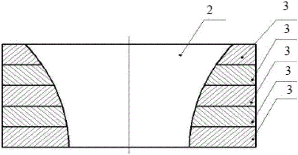
[0059] The framework adopts a multi-layer structure, such as image 3 As shown, the layers are fixed together by screws.

[0060] The cavity 2 in the frame is transparent up and down and is trumpet-shaped.

[0061] Wherein the prestressed film 4 and the acoustic material 5 are alternately placed inside the cavity 2 until the cavity 2 is filled.

[0062] Each layer of prestressed film 4 in the cavity 2 adopts the same type and material, and each layer of acoustic material 5 adopts the same structure type and material.

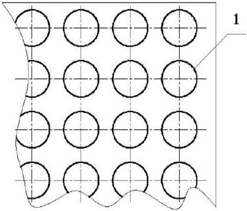
[0063] Wherein each layer of prestressed film 4 is a complete circular film, Figure 9 It is a partial enlarged view of the prestressed film 4 .

[0064] Wherein each layer of acoustic material 5 is a round table with variable cross-section, the side wall of the round table matches the inner wall of the trumpet-shaped cavity 2, Figure 16 It is a partially ...

Embodiment 2

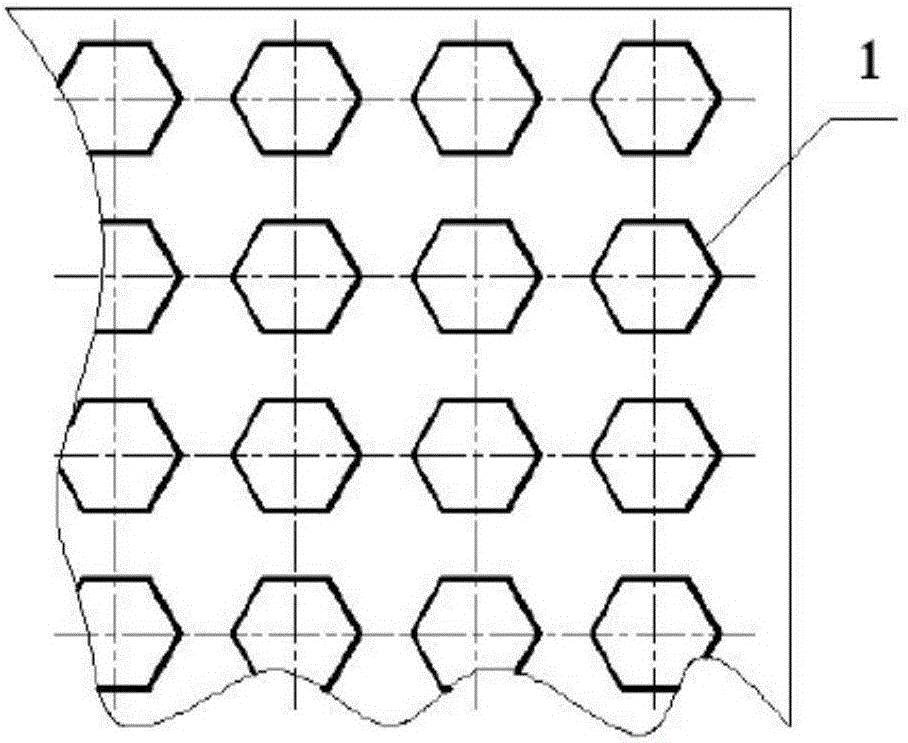
[0069] This embodiment is substantially the same as Embodiment 1, the only difference is that the prestressed film 4 adopts the hole type, Figure 10 It is a partial enlarged view of the prestressed film 4 .

Embodiment 3

[0071] This embodiment is substantially the same as Embodiment 1, the only difference is that the prestressed film 4 adopts the hole type, Figure 11 It is a partial enlarged view of the prestressed film 4 .


PUM


Abstract

The invention belongs to the technical field of acoustics, and discloses a novel ultra-thin acoustic wave impedance transformer. The transformer is characterized by comprising one or more impedance transformation units, wherein, each impedance transformation unit is composed of a frame, multiple layers of prestress films or multiple layers of prestress string nets, and multiple layers of acoustic material. A hole cavity which is penetrated through the upper and lower sides is formed in the frame, the prestress films or prestress string nets, and acoustic material are alternatively placed in the hole cavity, namely, from one end of the hole cavity, a layer of prestress film or string net, a layer of acoustic material, a layer of prestress film or string net and a layer of acoustic material are sequentially arranged in a circular manner until the hole cavity is filled. The hole cavity can be designed to different shapes, comprising variable cross-sections and uniform cross-sections. Before each layer of prestress film or string net is placed into the hole cavity, the prestress is required to be applied, and the size of the prestress is decided by the impedance expected to be achieved by the layer of prestress film or string net. The transformer can achieve the rapid variation of the impedance from low to high or from high to low, and the ultra-thin design is achieved.

Description

technical field [0001] The invention belongs to the technical field of acoustics and relates to a novel ultra-thin acoustic wave impedance converter. Background technique [0002] In recent years, the ultra-thin design of various products has become popular all over the world, including ultra-thin mobile phones, ultra-thin TV sets, ultra-thin computers, and ultra-thin, lightweight vibration and noise reduction devices for military and civilian use. In order to meet this demand, domestic and foreign scholars and engineers and technicians have carried out a lot of work, one of the bottlenecks is the ultra-thin design of the acoustic wave impedance transformer. For example, a loudspeaker is a kind of acoustic impedance converter, and its sound quality depends on the size of the end face of the loudspeaker. For a traditional speaker, the larger the diameter of the end face, the greater the thickness of the speaker. At present, in order to realize the ultra-thin design of the a...

Claims


Application Information

Patent Timeline
Patent Type & Authority Applications(China)
IPC IPC(8): H04R1/28
CPCH04R1/2815H04R1/2892H04R1/2876H04R1/2873G10K11/02H04R1/2803H04R1/44
Inventor 梅玉林王晓明梅艺璇王元秀
Owner DALIAN UNIV OF TECH
Learn More