How to use the quick release device

A purpose, technology of locking parts, applied in the field of high-acceleration drop impact test, can solve the problems of inconvenient hoisting of large-volume test pieces, high cost, limited lifting height, etc.

Inactive Publication Date: 2018-10-19
段正勇
View PDF7 Cites 0 Cited by
  • Summary
  • Abstract
  • Description
  • Claims
  • Application Information

AI Technical Summary

Problems solved by technology

[0005] An object of the present invention is to provide a pneumatic quick-release device, which has the advantages of compact structure, small size, light weight, simple and convenient operation, safety and reliability, and low cost, and is especially suitable for large size and heavy weight. The high-acceleration drop impact test of the test piece solves the existing problems in the prior art. When the hook of the common quick releas

Method used


Image

  • How to use the quick release device
  • How to use the quick release device
  • How to use the quick release device

Examples


Embodiment 1

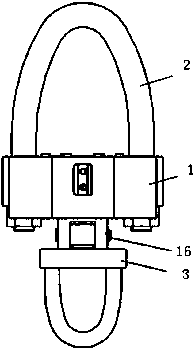
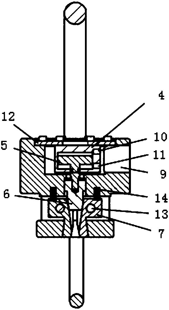
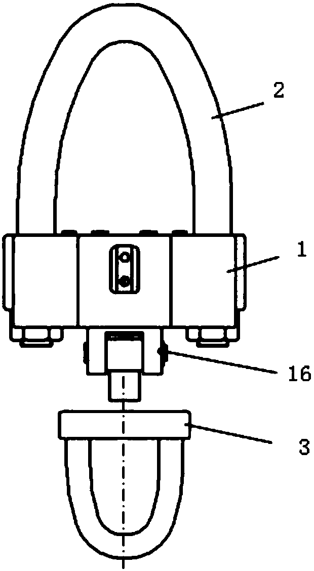
[0027] figure 1 The front view before the release of the pneumatic quick-release device provided by the embodiment of the present invention; figure 2 for figure 1 Front sectional view of the pneumatic quick-release device shown; image 3 The front view after the release of the pneumatic quick release device provided by the embodiment of the present invention; Figure 4 for image 3 The front sectional view of the pneumatic quick-release device shown; Figure 1-4 As shown, the pneumatic quick-release device provided in this embodiment includes: a main body 1, a connecting portion 16 is provided at one end of the main body 1, a driving mechanism moving in the vertical direction is provided in the main body 1, and a lock is provided in the connecting portion 16. Tightening part 7, the driving mechanism moves downward or upward in the tapered hole 15 at one end of the locking part 7 to drive the diameter of the other end of the locking part 7 to become larger or smaller, and ...

Embodiment approach

[0045] As the first embodiment of the present invention, when the present invention adopts the air pressure-driven connection between the cylinder 4 and the cylinder piston 5, the cylinder 4 adopts a double-acting cylinder, and the upper gas passage 10 and the lower gas passage 11 of the cylinder 4 pass through the air pipe through hole 9 Connect with the air supply pipe respectively.

[0046] Before use, first connect the upper lifting lug 2 to the crane, and connect the lower lifting lug 3 to the test piece to be lifted or released, start the crane, and then perform the movement according to the following steps:

[0047] (i) The upper gas channel 10 of the cylinder 4 exhausts, the lower gas channel 11 intakes air, the cylinder piston 5 drives the thimble 6 to move upward to the dead point, and under the action of the return spring 14, the lower end of the locking member 7 shrinks to close For the purpose, the inverted taper hole 8 of the lower lifting lug 3 can be pushed int...


PUM


Abstract

The invention provides a pneumatic quick-releasing device. The pneumatic quick-releasing device comprises a main body; a connection part is connected to one end of the main body; the main body is internally provided with a driving mechanism moving in the perpendicular direction; the connecting part is internally provided with a locking piece; the driving mechanism moves in a conical hole in one end of the locking piece downwards or upwards so as to drive the diameter of the other end of the locking piece to be increased or decreased; and the other end of the locking piece locks or releases an inverted conical hole of a lower lifting lug. According to the pneumatic quick-releasing device, when the driving mechanism moves downwards or upwards in the conical hole of the locking piece, the diameter of the other end of the locking piece is made to be increased or decreased, accordingly, the purpose of quickly locking or releasing the lower lifting lug is achieved; the pneumatic quick-releasing device is quick in action response, precise in operation and small in size, and the efficiency of the lifted weight is large; compared with a falling impact test device provided by the prior art, the impact accelerated speed is higher; and the structural design is simple, and using is safe and reliable.

Description

technical field [0001] The invention relates to the technical field of high-acceleration drop impact test, in particular to a method for using a quick-release device. Background technique [0002] At present, in the field of high-acceleration drop impact test technology, the test is usually carried out with the help of existing lifting devices such as bridge cranes for relatively heavy and relatively large test pieces. [0003] During the test, the bridge crane is connected to a quick-release mechanism, and the hook of the mechanism is connected to the rope binding the test piece. After the crane is started to lift to the set height, the quick-release mechanism is operated to let go of the rope and release the test piece. The test piece is made to collide with the anvil table directly below to realize the drop high-acceleration impact test. In addition, the high-acceleration drop impact test can also be performed directly using special drop impact test equipment. [0004] ...

Claims


Application Information

Patent Timeline
IPC IPC(8): B66C1/10G01M7/08
CPCB66C1/10G01M7/08
Inventor 段正勇李阳唐传胜韩军良
Owner 段正勇
Why Eureka
Try Eureka