Device and method for sealing and locking liquid-cooled radiator nozzle

A locking device, heat sink technology, applied in the use of liquid/vacuum for liquid tightness measurement, by detecting the appearance of fluid at the leak point, sleeve/socket connection, etc., to avoid damage to components and protect them from being compressed bad effect

Active Publication Date: 2018-02-13
SHIDAI ELECTRIC FACTORY ZHUZHOU ELECTRIC LOCOMOTIVES INST MIN OF RAILWAYS
View PDF7 Cites 0 Cited by
  • Summary
  • Abstract
  • Description
  • Claims
  • Application Information

AI Technical Summary

Problems solved by technology

[0008] Since the above invention does not have structures such as a fixed support, a fastening shaft, and a lock nut, it is difficult for the sealing device to lock the water nozzle while sealing the water nozzle

Method used


Image

  • Device and method for sealing and locking liquid-cooled radiator nozzle
  • Device and method for sealing and locking liquid-cooled radiator nozzle
  • Device and method for sealing and locking liquid-cooled radiator nozzle

Examples


Embodiment 1

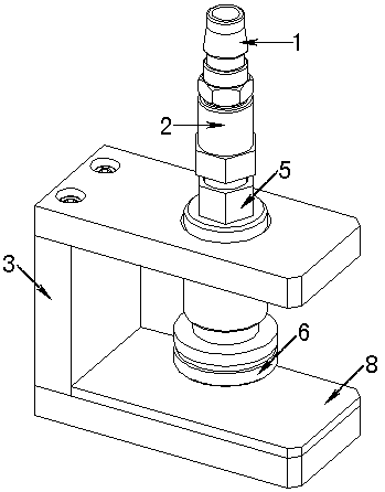
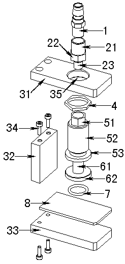
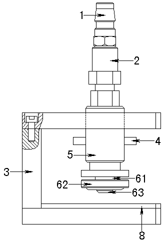
[0037] Such as figure 1 with figure 2 As shown, the fixed support 3 includes an upper guard plate 31 , a support block 32 and a base 33 , and the upper guard plate 31 is provided with a threaded hole 35 . The transition joint 2 connects the quick joint 1 and the sealing shaft 6 into a whole, and the fastening shaft 5 is sleeved on the whole, so that the whole can move up and down in the through hole in the middle of the fastening shaft 5 . The fastening shaft 5 is movably connected in the threaded hole 35 of the upper guard plate 31 of the fixed support 3 through threads, and the fastening shaft 5 can be moved downward by rotating the fastening shaft 5, so that the fastening chassis at the lower end of the fastening shaft 5 53 abuts on the shaft disc 62 of the sealing shaft 6, so that the shaft disc 62 also moves downwards.

[0038]The upper guard plate 31, the support block 32 and the base 33 are all cuboid, and one side of the upper guard plate 31 and the base 33 has moun...

Embodiment 2

[0049] Such as Figure 4 with Figure 5 As shown, the water nozzle 91 of the liquid cooling radiator 9 in the first embodiment is front, while the water nozzle 91 of the liquid cooling radiator 9 in the second embodiment is side. Since the structure of the liquid cooling radiator 9 and the orientation of the water nozzle 91 are different, the devices and methods for sealing and locking the water nozzle 91 of the radiator are also different.

[0050] Such as Figure 5 As shown, the locking screw 10 includes a screw head 101 and a locking head 102, and the upper guard plate 31 and the support block 32 of the fixed support 3 are provided with threaded holes 35, and the locking screw 10 is mounted on the fixed support through thread fit. In the threaded hole 35 of the upper guard plate 31 of 3, the fastening nut 51 is installed in the threaded hole 35 of the support block 32 of the fixed support 3 by the threads on the threaded pipe 52. The lower end of the locking screw 10 is ...


PUM


Abstract

The invention relates to a device and method for sealing and locking a water nozzle of a liquid-cooled radiator. A quick connector is arranged at the upper end of a sealing device, a fastening shaft is movably connected with a fixed support seat, a sealing shaft passes through a through hole formed in the middle of the fastening shaft and is connected with a transit joint, and the transit joint is also connected with the quick connector; and by adjusting the position of the fastening shaft on the fixed support seat, the position of the sealing shaft can be limited, the sealing shaft is enabled to prop against the water nozzle of the liquid-cooled radiator by the fastening shaft, and a sealed space is formed between a shaft disc and the liquid-cooled radiator. According to the device and the method, a guide pillar is enabled to prop against the water nozzle by rotating the fastening shaft, and the shaft disc is pressed downwards by a fastening chassis, so that the shaft disc and the liquid-cooled radiator can be sealed in a static state by a gasket in a groove of the shaft disc; and the fastening shaft is prevented from rotating by screwing down a lock nut, so that the sealing shaft is limited and locked by the fastening chassis of the fastening shaft, the shaft disc and the liquid-cooled radiator can be well sealed in the static state by the gasket, and the phenomena of loosening and air leakage are avoided.

Description

technical field [0001] The invention relates to a sealing and locking device and a sealing method of a liquid cooling radiator, in particular to a sealing and locking device and a sealing method of a liquid cooling radiator with a circular nozzle. Background technique [0002] The input joint used to connect the air source and the radiator used in the air tightness test of the existing liquid-cooled radiator adopts a general-purpose water nozzle joint and a quick joint. The water nozzle joint needs to be threaded to cooperate with the radiator. Therefore, Liquid-cooled radiator inlet / outlet nozzles are usually designed with an internal thread structure, which is suitable for air tightness tests, but there is no such thing as a special circular nozzle structure proposed by the customer and no effective screw holes around the nozzle structure. Appropriate sealing scheme, which will lead to insufficient sealing and air leakage during the air tightness test, which will seriously...

Claims


Application Information

Patent Timeline
Patent Type & Authority Patents(China)
IPC IPC(8): G01M3/10G01M3/02F16L21/00
CPCF16L21/00G01M3/02
Inventor 余翔贾世童蔡洪杰
Owner SHIDAI ELECTRIC FACTORY ZHUZHOU ELECTRIC LOCOMOTIVES INST MIN OF RAILWAYS
Why Eureka
Try Eureka