Non-contact electric-arc-furnace continuous temperature measuring gun structure

A non-contact, electric arc furnace technology, applied in the direction of measuring devices, optical radiation measurement, radiation pyrometry, etc., can solve the problem of insufficient support of dynamic metallurgical model data, inability to realize continuous online temperature measurement, infrared temperature sensor coaxial, etc. Problems, to achieve the effect of long-distance temperature measurement, small attenuation of optical radiation, and prolong life

Inactive Publication Date: 2016-08-31
CISDI ENG CO LTD
7 Cites 6 Cited by

AI-Extracted Technical Summary

Problems solved by technology

[0002] In metallurgical processes such as electric arc furnaces, LF refining furnaces, and converters that produce foamy slag layers, temperature measurement and sampling are required. The existing technology generally uses manual operations, which require power-off operations and generate probe consumption.
There is also an automatic temperature measurement and sampling device for the furnace door, which needs to insert the probe into the molten steel, and continuous ...

Method used

In sum, the present invention increases and surrounds with high-temperature hot gas flow at the outer layer of supersonic jet, makes center supersonic jet expand and attenuation smaller, and supersonic jet is longer, and the ability of blowing away molten steel level slag layer is stronger . The temperature...

Abstract

The invention provides a non-contact electric-arc-furnace continuous temperature measuring gun structure and belongs to the iron and steel smelting technology field. The structure comprises an annular hole cluster spray gun and an infrared temperature measurement probe. The cluster annular hole spray gun is provided with a cooling water sleeve, a supersonic speed airflow nozzle, a small hole with flow and burning and a peep pipe. The infrared temperature measurement probe is installed in the peep pipe of the annular hole cluster spray gun. A protection gas is filled in the peep pipe. A supersonic speed airflow formed by the annular hole cluster spray gun blows a molten pool slag layer so that a melt surface is exposed to the infrared temperature measurement probe. During a smelting process of generating foam slags by an electric-arc furnace, non-contact continuous automatic temperature measurement in an uninterruptible power production process can be realized.

Application Domain

Radiation pyrometry

Technology Topic

AirflowSmelting process +7

Image

  • Non-contact electric-arc-furnace continuous temperature measuring gun structure
  • Non-contact electric-arc-furnace continuous temperature measuring gun structure
  • Non-contact electric-arc-furnace continuous temperature measuring gun structure

Examples

  • Experimental program(1)

Example Embodiment

[0023] The preferred embodiments of the present invention will be described in detail below; it should be understood that the preferred embodiments are only for illustrating the present invention, not for limiting the protection scope of the present invention.
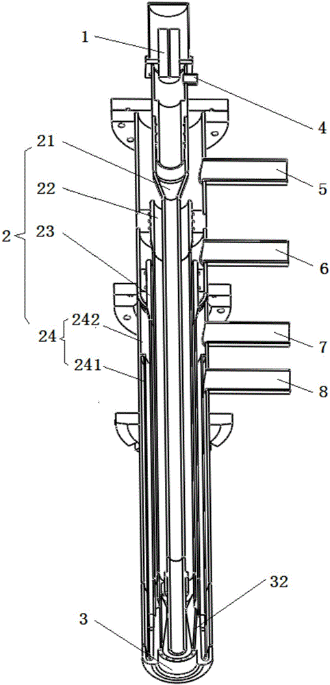
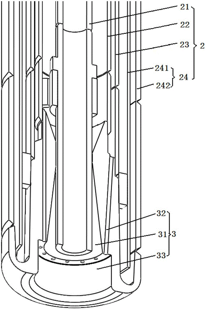
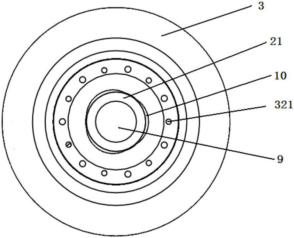
[0024] Such as Figure 1-3 As shown, a non-contact electric arc furnace continuous temperature measuring gun structure includes a ring-hole cluster spray gun and an infrared temperature measuring probe 1. The ring-hole cluster spray gun is equipped with a cooling water jacket 24, a supersonic airflow nozzle, and a wake follower. Hole 32 and peep tube 21; in the structure of the present invention, the barrel 2 of the ring-hole cluster spray gun is mainly composed of a peep tube 21, a main air tube 22, an air pipe 23, a water-cooled inner tube 241 and a water-cooled outer tube 242 that are coaxially arranged , And correspondingly provided with a protective air inlet 4, a main air inlet 5, an accompanying air inlet 6, a cooling water inlet 7, and a cooling water outlet 8. The water-cooled inner pipe 241 and the water-cooled outer pipe 242 constitute the cooling water jacket 24 The key of the present invention is that the infrared temperature measuring probe 1 is installed in the peep tube 21 of the ring-hole cluster spray gun. In this way, the supersonic gas stream formed by the ring-hole cluster spray gun blows open the molten pool slag layer, exposing the surface of the molten liquid in front of the infrared temperature probe, and implements non-contact continuous automatic temperature measurement for the smelting process of the foamed slag produced by the electric arc furnace . Further, protective gas is introduced into the sight tube 21; in this way, the supersonic clustered main air flow blown out by the ring-hole clustering spray gun wraps the temperature measuring protective gas in the center, blows away the foamed slag on the molten steel surface, and forms a secondary surface of the molten steel. Temperature measurement channel to the probe. Preferably, when argon (Ar) is used as the protective gas, the attenuation of light radiation is small, and the interference to the temperature measurement accuracy is small.
[0025] It should be particularly noted that the automatic temperature measuring device of the present invention is not only used in electric arc furnaces, but also in smelting equipment that easily produces foamy slag such as LF refining furnaces or converters, and can also be used in smelting The purpose of non-contact continuous automatic temperature measurement of the process.
[0026] In this embodiment, the supersonic airflow nozzle is a cluster nozzle 3, which is provided with a central hole 31, a wake-tracing orifice 32, and a directional chamber 33. The main air pipe 22, the accompanying air pipe 23, and the water-cooled outer pipe 242 are respectively It is welded to the cluster nozzle 3, and the sight tube 21 is plugged into the cluster nozzle 3.
[0027] Specifically, in the structure of the present invention, there is an orientation chamber 33 at the end of the cluster nozzle, a central hole 31 and a plurality of wake and combustion small holes 32 evenly distributed around the central hole 31 are opened at the bottom, and the sight tube 21 is provided The protective gas outlet 9, the main gas outlet 10 provided on the main air pipe 22, and the wake accompanying gas outlet 321 provided on the cluster nozzle 3 are all set at the bottom of the directional chamber 33; the wake accompanying combustion small holes 32 are located in the main air pipe 22 In this way, the accompanying gas introduced from the accompanying gas inlet 6 enters the orifice 32 of the trailing burner through the accompanying pipe, and flows out of the trailing accompanying gas from the trailing burner outlet 321, and can be lower The flow velocity of is around the main air pipe 22 from the main air outlet 10 to form a cluster jet. When fuel gas is used as the wake gas, the high-temperature gas produced by the combustion further compresses the main gas flow to form a more distant cluster jet.
[0028] In this embodiment, the peep tube 21 is inserted into the center hole 31, so that the inner wall of the center hole 31 of the cluster nozzle 3 and the outer wall of the peep tube 21 form a variable cross-section loop channel that accelerates the flow rate of the main gas to supersonic speed, so that When the main gas passes through, it gets supersonic acceleration.
[0029] In summary, the present invention increases the surrounding high-temperature hot air flow on the outer layer of the supersonic jet, so that the central supersonic jet has less expansion and attenuation, the supersonic jet is longer, and the ability to blow open the molten steel slag layer is stronger. The temperature measurement protection gas wrapped in the center of the supersonic main airflow forms a temperature measurement channel to reach the molten steel surface. When applied to online temperature measurement of electric arc furnace smelting, it can realize continuous non-contact temperature measurement of molten steel.
[0030] The embodiment of the present invention applied to electric arc furnace smelting has achieved the following effects:
[0031] 1) Compared with the existing nozzle structure, the manufacturing difficulty of the nozzle structure of this embodiment is significantly reduced;
[0032] 2) Compared with the existing gun body structure, the gun body structure of this embodiment has a more reasonable structure, simpler assembly, and more convenient replacement.
[0033] 3) Compared with the existing temperature measuring gun, the ring-hole cluster spray gun of this embodiment realizes non-contact continuous online temperature measurement;
[0034] 4) Compared with the temperature measurement technology, the ring-hole cluster spray gun of this embodiment has stronger anti-interference ability.
[0035] Finally, it should be noted that the above embodiments are only used to illustrate the technical solutions of the present invention and not to limit them. Although the present invention has been described in detail with reference to the preferred embodiments, those of ordinary skill in the art should understand that the technical solutions of the present invention can be implemented Modifications or equivalent replacements without departing from the purpose and scope of the technical solution should be covered by the scope of the claims of the present invention.

PUM

no PUM

Description & Claims & Application Information

We can also present the details of the Description, Claims and Application information to help users get a comprehensive understanding of the technical details of the patent, such as background art, summary of invention, brief description of drawings, description of embodiments, and other original content. On the other hand, users can also determine the specific scope of protection of the technology through the list of claims; as well as understand the changes in the life cycle of the technology with the presentation of the patent timeline. Login to view more.

Similar technology patents

Integrated damping switch separate layer fracturing device and method

ActiveCN113027408Areduce erosionImprove closing effect
Owner:SHANDONG BOSAITE PETROLEUM TECH CO LTD

Valve element assembly of high-flow safety valve

ActiveCN104153794AReduce erosionIncreased seal reliability and service life
Owner:JULONG GROUP WUHU XINGLONG HYDRAULIC

Sea water pump

Owner:芜湖谱瑞电子科技有限公司
Why Eureka
Try Eureka