Light guide and light emitting device

A technology of light-emitting device and light guide body, applied in the direction of light guide, optics, optical components, etc., can solve problems such as flicker, and achieve the effect of suppressing flicker

Active Publication Date: 2020-01-21
ORMON CORP
View PDF9 Cites 0 Cited by
  • Summary
  • Abstract
  • Description
  • Claims
  • Application Information

AI Technical Summary

Problems solved by technology

[0011] Therefore, in the region where the first reflective region c and the second reflective region d overlap, the arrangement density of the first reflective patterns 5 a and the arrangement density of the second reflective patterns 6 a are rough. As a result, the light guide plate 104 The issue of flicker occurs when the text area of ​​the English "OPEN" or "CLOSE" is illuminated on the light exit surface 145

Method used


Image

  • Light guide and light emitting device
  • Light guide and light emitting device
  • Light guide and light emitting device

Examples


Embodiment approach 1

[0086] Below, based on Figure 1 to Figure 9 Embodiments of the present invention will be described. In this embodiment mode, an example of a light emitting device including the light guide of the present invention will be described.

[0087] [Structure of Light-Emitting Device 1 ]

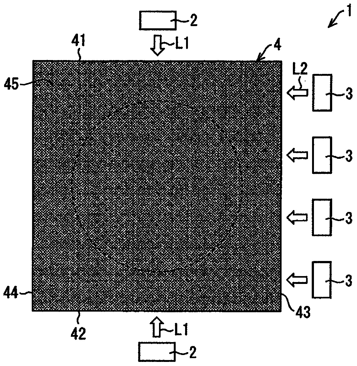
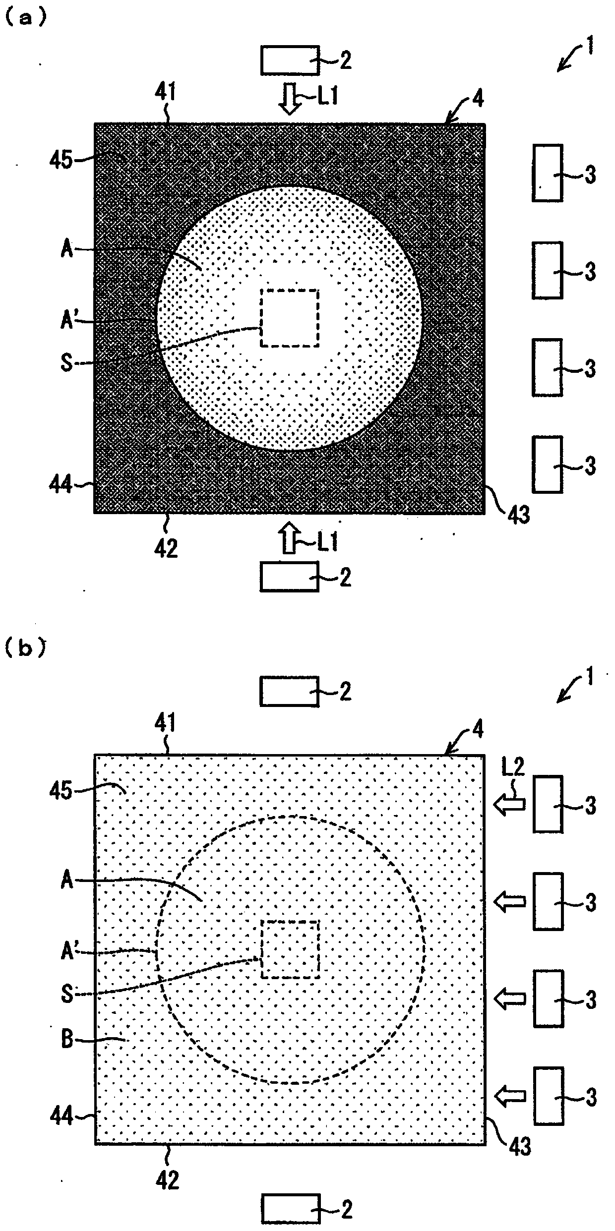
[0088] figure 1 It is a plan view showing the light emitting device 1 including the light guide plate (light guide body) 4 of the present embodiment. This light emitting device 1 is used as various surface light emitting devices such as an illuminated push button switch provided on an elevator operation panel attached to a wall surface of an elevator car, for example.

[0089] Such as figure 1 As shown, the light emitting device 1 includes a first light source 2 , a second light source 3 and a light guide plate 4 .

[0090] (first light source 2)

[0091] The first light source 2 is a light emitting element that makes light L1 incident on both side surfaces 41 and 42 of the light guide pla...

Deformed example 1

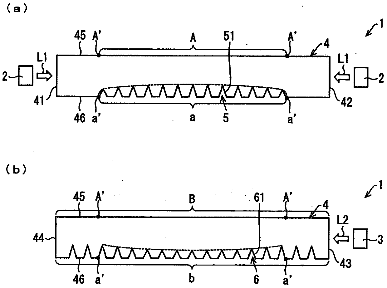
[0148] In the above description, the structure in which triangular prism-shaped patterns are formed on the back surface 46 of the light guide plate 4 as the first reflective pattern 5 and the second reflective pattern 6 has been described, but the first reflective pattern 5 and the second reflective pattern 6 The shape is not particularly limited. For example, the first reflective pattern 5 and the second reflective pattern 6 may be spindle-shaped when viewed from a direction perpendicular to the light exit surface 45 of the light guide plate 4 .

[0149] Figure 7 (a) is a perspective view of the first reflective pattern 5a, Figure 7 (b) is a plan view of the first reflective pattern 5a, Figure 7 (c) is a side view of the first reflective pattern 5a.

[0150] Such as Figure 7 As shown in (a) to (c), when viewed from the vertical direction of the light exit surface 45 of the light guide plate 4, the first reflective pattern 5a is positioned positively to the optical axi...

Deformed example 2

[0159] In addition, in the above description, the configuration in which the light L1, L2 is reflected by the first reflective pattern 5 and the second reflective pattern 6 formed on the back surface 46 of the light guide plate 4 to emit from the light exit surface 45 has been described. However, it may be configured to refract the lights L1 and L2 to emit from the light emitting surface 45 .

[0160] The refraction type light guide plate (light guide body) that refracts the light L1, L2 includes a first refraction structure that is arranged with a plurality of first refraction structures that refract the light L1 incident from the first light source 2 and emit it from the light exit surface 45. region, and the second refraction region in which the light L2 incident from the second light source 3 is refracted and emitted from the light exit surface 45 is arranged, when viewed from the vertical direction of the light exit surface 45, the second refraction region At least a part...


PUM


Abstract

A light guide and a light emitting device are capable of suppressing a flicker during light emission in a region where light emitting regions overlap. A light guide plate (4) according to the present invention includes a first reflection array (R1) configured to arrange a plurality of first reflection patterns (5) reflecting light incident from a first light source in a row shape, a second reflection column (R2) which is configured to arrange a plurality of second reflection patterns (6) reflecting light incident from a second light source different from the first light source in a direction of an optical axis in a row shape, the first reflection pattern (R1) and the (R2) are arranged substantially parallel to each other, and at least one of the first reflective rows (R1) is sandwiched between the second reflective rows (R2).

Description

technical field [0001] The present invention relates to a light guide body that guides light incident from a side and emits it from a light exit surface, and a light emitting device including the light guide body. Background technique [0002] Conventionally, it is known that light emitted from a light source is incident on a side surface of a light guide plate, reflected by a reflective pattern (reflective structure) arranged on the light guide plate, and thereby emitted from the surface (light emitting surface) of the light guide plate. light emitting device. [0003] Figure 11 (a) is a plan view showing a conventional light emitting device 101, Figure 11 (b) means Figure 11 (a) is a plan view of the arrangement of the first reflective pattern 105 and the second reflective pattern 106 inside the dotted line frame S shown in (a). [0004] Such as Figure 11 (a) and Figure 11 As shown in (b), the light-emitting device 101 described in Patent Document 1 is equipped with ...

Claims


Application Information

Patent Timeline
Patent Type & Authority Patents(China)
IPC IPC(8): G02B6/00
CPCG02B6/0025G02B6/0031G02B6/0036G02B6/006G02B6/0068G02B6/0091
Inventor 奥田满筱原正幸田上靖宏
Owner ORMON CORP
Why Eureka
Try Eureka