
Power compensation method and system for wind power system

A wind power system and power compensation technology, applied in reactive power compensation, reactive power adjustment/elimination/compensation, wind power generation, etc., can solve problems such as slow response speed, inability to adjust active power, and inability to meet reactive power. Suppress voltage flicker, stabilize output, and ensure stable effect

Active Publication Date: 2015-05-27
BYD CO LTD
View PDF2 Cites 0 Cited by
  • Summary
  • Abstract
  • Description
  • Claims
  • Application Information

AI Technical Summary

Problems solved by technology

[0003] There are mainly two existing reactive power compensation methods: one method is to use a mechanical method to switch capacitors for reactive power compensation. The problem with this method is that the response speed is slow and it cannot meet the rapidly changing reactive power in wind power. Therefore, the reactive power in the grid cannot be effectively compensated; another method is to use SVC (Static Var Compensator, static var compensation) device for reactive power compensation, although this method can compensate the reactive power of the grid Perform fast differential adjustment, but it is impossible to accurately adjust the reactive power of the wind power system, let alone the active power, and certain harmonics will be generated during the power compensation process

Method used


Image

  • Power compensation method and system for wind power system
  • Power compensation method and system for wind power system

Examples


Embodiment Construction

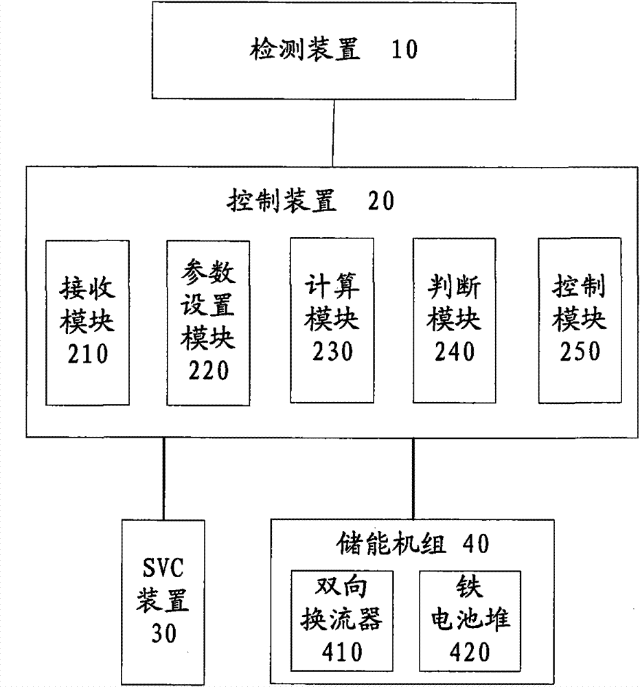
[0012] Embodiments of the present invention are described in detail below, examples of which are shown in the drawings, wherein the same or similar reference numerals designate the same or similar elements or elements having the same or similar functions throughout. The embodiments described below by referring to the figures are exemplary only for explaining the present invention and should not be construed as limiting the present invention.

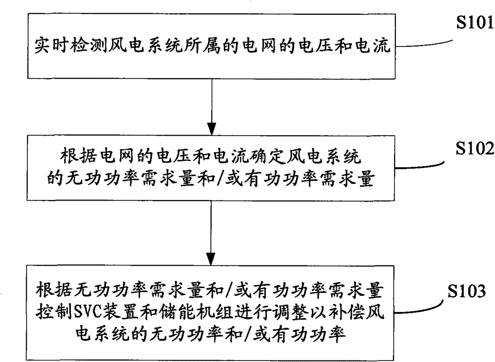
[0013] Such as figure 1 Shown is a flow chart of a power compensation method for a wind power system according to an embodiment of the present invention, and the method includes the following steps:

[0014] Step S101, real-time detection of the voltage and current of the grid to which the wind power system belongs.

[0015] Step S102, determining the power demand of the wind power system according to the voltage and current of the grid.

[0016] Specifically, firstly, the power of the wind power system is determined according to the v...


PUM


Abstract

The invention discloses a power compensation method and a system for a wind power system, wherein the method comprises the following steps: detecting the voltage and current of a power grid belonging to the wind power system in real time; determining the power requirement quantity of the wind power system according to the voltage and current of the power grid, wherein the power requirement quantity comprises reactive power requirement quantity and / or active requirement quantity; and controlling an SVC (static var compensator) device and / or an energy storage unit to regulate so as to compensate the reactive power / or active power of the wind power system. According to the invention, through the compensation device combined by the SVC device and the energy storage unit, not only can the reactive power required in the wind power system be compensated smoothly, rapidly and accurately, but also harmonic wave can not be generated in the compensation process, at the same time, the active power can be provided, the output of the wind power system can be stablized, the voltage flicker is inhibited effectively, and the stability of the power grid is ensured.

Description

technical field [0001] The invention relates to the technical field of wind power generation, in particular to a power compensation method and system for a wind power system. Background technique [0002] In the process of wind power generation, whether it is in normal operation or in shutdown state, the wind turbine needs to absorb reactive power from the grid, so it is very important to perform reactive power compensation in the wind power system. [0003] There are mainly two existing reactive power compensation methods: one method is to use a mechanical method to switch capacitors for reactive power compensation. The problem with this method is that the response speed is slow and it cannot meet the rapidly changing reactive power in wind power. Therefore, the reactive power in the grid cannot be effectively compensated; another method is to use SVC (Static Var Compensator, static var compensation) device for reactive power compensation, although this method can compensat...

Claims


Application Information

Patent Timeline
Patent Type & Authority Patents(China)
IPC IPC(8): H02J3/18H02J3/01
CPCY02E10/76Y02E40/30Y02E40/40
Inventor 邓林旺曾宇邓亚明高云秀
Owner BYD CO LTD
Learn More