Drive circuit, automotive lamps

A driving circuit and driving voltage technology, which is applied in the direction of headlights, electric light sources, vehicle components, etc., can solve the problems of high cost and large number of circuit components, and achieve the effect of suppressing flicker

Active Publication Date: 2020-08-21
KOITO MFG CO LTD
View PDF2 Cites 0 Cited by
  • Summary
  • Abstract
  • Description
  • Claims
  • Application Information

AI Technical Summary

Problems solved by technology

However, the buck-boost converter has a problem of high cost due to the large number of circuit elements compared with the buck converter

Method used


Image

  • Drive circuit, automotive lamps
  • Drive circuit, automotive lamps
  • Drive circuit, automotive lamps

Examples


Embodiment Construction

[0039] Next, a drive circuit and a vehicle lamp according to embodiments of the present invention will be described with reference to the drawings.

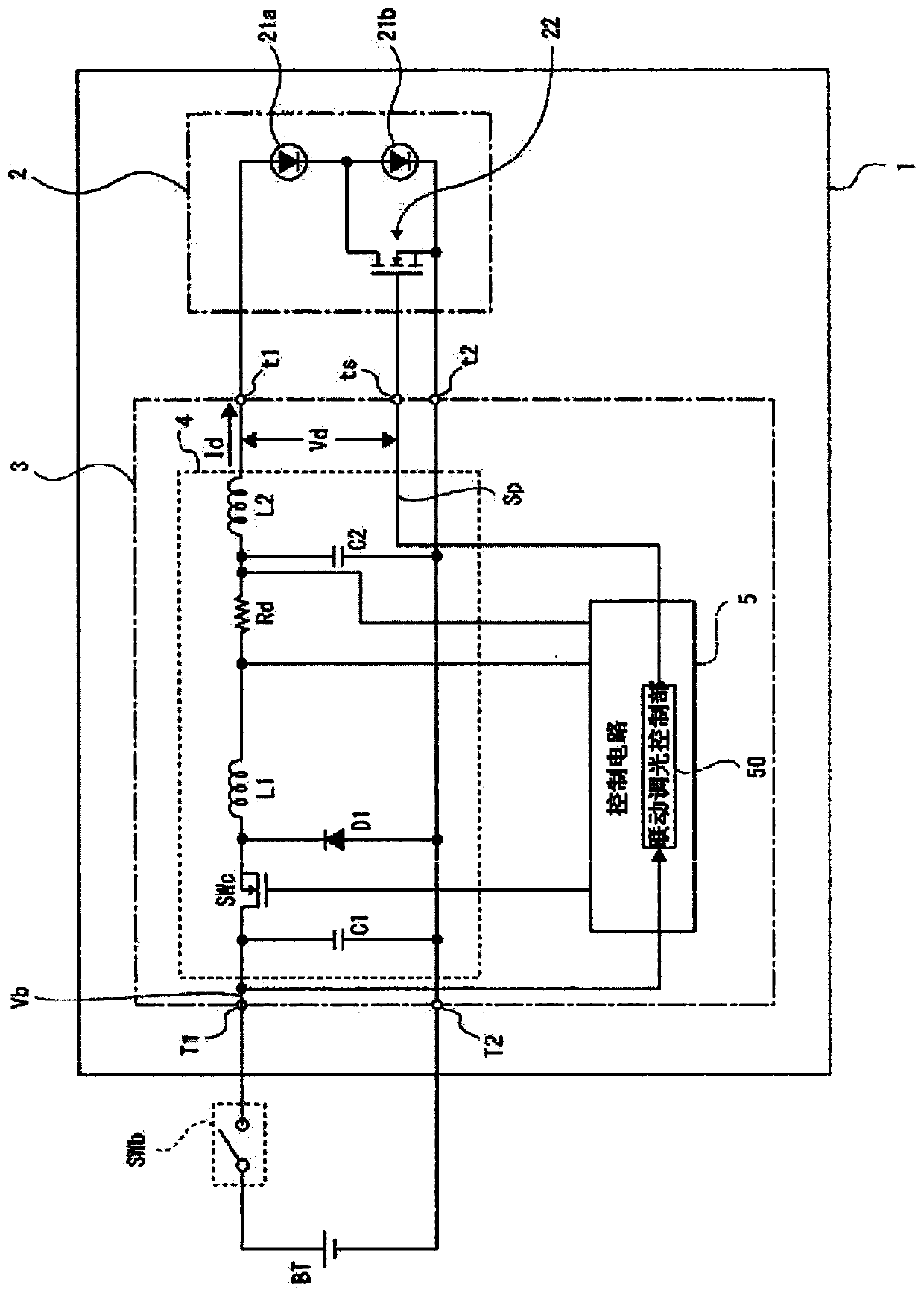
[0040] figure 1 It is a circuit block diagram for explaining the schematic internal structure of the vehicle lamp 1 which is 1st Embodiment. In addition, in figure 1 In FIG. 1 , an on-vehicle battery BT provided in the vehicle outside the vehicular lamp 1 and an input switch SWb for turning on and off the input voltage from the on-vehicle battery BT to the vehicular lamp 1 are shown together.

[0041] In this example, the premise is that the output voltage (battery voltage) of the battery BT is about 12V.

[0042] The vehicle lamp 1 is a headlight (vehicle headlamp) in which a pair of two lamps are arranged on the left and right sides of the front end of the vehicle.

[0043] As shown in the figure, the vehicle lamp 1 includes: a light emitting unit 2 having a plurality of semiconductor light emitting elements 21; and a drive ...


PUM


Abstract

Prevents semiconductor light-emitting elements from becoming completely extinguished due to a drop in input voltage, and suppresses flicker. The driving circuit according to the present invention is provided in a vehicle lamp and drives a light emitting unit having a plurality of semiconductor light emitting elements connected in series, and includes a driving voltage generating unit that steps down an input voltage from a battery and generates A drive voltage for driving the semiconductor light emitting elements; a control unit capable of on-off control of bypass switches connected in parallel to some of the semiconductor light emitting elements, when the input voltage is equal to or less than a first threshold value A dimming mode is selected, and in this dimming mode, linked dimming control is performed in which the ON ratio of the bypass switch per unit time is increased as the input voltage decreases.

Description

technical field [0001] The present invention relates to a drive circuit provided in a vehicular lamp and driving a light-emitting portion having a plurality of semiconductor light-emitting elements connected in series; and a vehicular lamp including the light-emitting portion and the drive circuit. Background technique [0002] As a light emitting unit of a vehicle lamp, for example, a semiconductor light emitting element such as an LED (Light Emitting Diode, light emitting diode) is used. As the light emitting unit in this case, a plurality of semiconductor light emitting elements may be connected in series due to insufficient light quantity due to only one chip of the semiconductor light emitting element. For example, a light emitting unit in which two LED chips are connected in series is often used in a headlight lamp for a vehicle. [0003] The VF (forward voltage) of white LEDs used in headlights is about 3.5V per chip, and the VF of LED circuits connected in series in...

Claims


Application Information

Patent Timeline
Patent Type & Authority Patents(China)
IPC IPC(8): H05B45/325H05B44/00
CPCH05B45/10H05B45/375F21S41/255F21S41/336F21S41/663F21S41/148F21S41/675H05B45/48Y02B20/30F21S41/30F21S41/141B60Q1/1415
Inventor 市川知幸
Owner KOITO MFG CO LTD
Why Eureka
Try Eureka