Magnetic control type arc furnace transformer device

A technology for electric arc furnace transformers and magnetron reactors, which is applied in the direction of electric heating devices, electrical components, heating through discharge, etc., can solve the problem of reducing the stability of the output voltage of the power supply system, the sudden rise and fall of the voltage of the power supply system, and affecting the normal use of other users Electricity and other problems, to achieve the effect of shortening the smelting time, convenient application and operation, convenient and flexible layout

Active Publication Date: 2012-03-21
DANDONG XINTAI ELECTRIC
View PDF0 Cites 0 Cited by
  • Summary
  • Abstract
  • Description
  • Claims
  • Application Information

AI Technical Summary

Problems solved by technology

[0004] The short circuit or open circuit of the electrodes will cause the three-phase unbalance, causing a huge current impact on the electric arc furnace transformer, causing the instantaneous voltage rise and fall of the power supply system, reducing the stability of the output voltage of the power supply system, and affecting the normal power consumption of other users
[0005] 2. Generate a lot of harmonics
[0006] The three-phase imbalance causes the arc impedance to be unstable, so that the current waveform no longer changes regularly, and a large number of harmonics appear. The total harmonic distortion rate in the electric arc furnace working system exceeds 5% of the national standard. Reaching 25%, the power grid system suffers a lot of harmonic pollution and makes voltage distortion more complicated
[0007] 3. Cause voltage fluctuation and flicker
These requirements not only increase the difficulty of manufacturing the transformer, but also increase the cost of the system, and the above-mentioned problems in the operation of the electric arc furnace have not been solved.

Method used


Image

  • Magnetic control type arc furnace transformer device
  • Magnetic control type arc furnace transformer device
  • Magnetic control type arc furnace transformer device

Examples


Embodiment Construction

[0024] The specific structure and application method of the present invention will be described in detail in conjunction with the accompanying drawings.

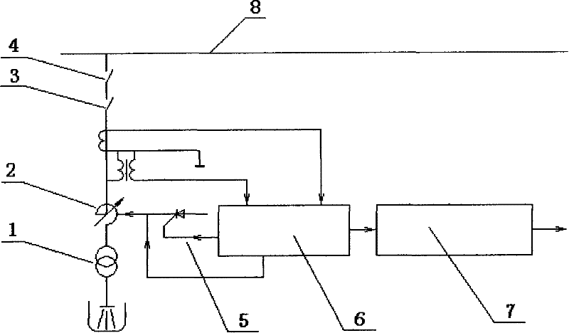
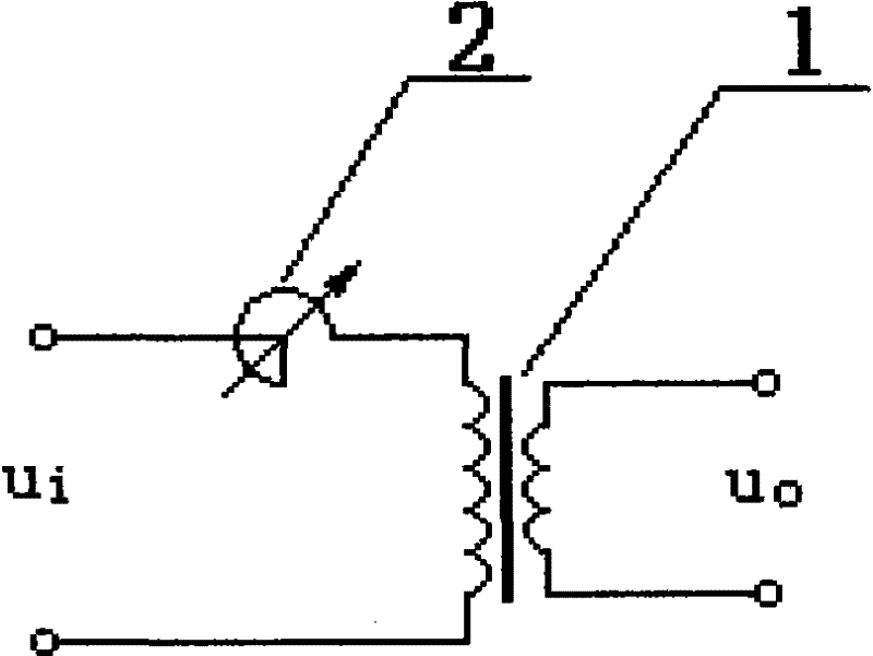
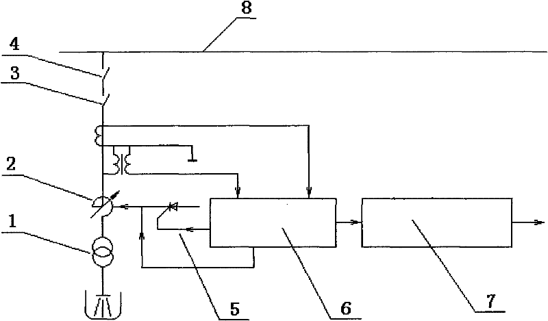
[0025] A magnetically controlled electric arc furnace transformer device, such as figure 1 and figure 2 Shown: According to the capacity of the electric arc furnace, select the electric arc furnace transformer with appropriate specifications and models, select the magnetic control reactor with appropriate specifications and models according to the capacity of the electric arc furnace, and connect the three-phase windings on the primary side of the three-phase electric arc furnace transformer 1 with the magnetic control reactor in series 2, electric arc furnace transformer 1 and magnetron reactor 2 are connected in series to the 10kV high-voltage load switch 3 in the conventional standard electric control cabinet, the high-voltage load switch 3 is connected to the isolation switch 4, and the isolation switch 4 is connected t...


PUM


Abstract

The invention relates to a magnetic control type arc furnace transformer device. The device is characterized in that the device comprises two parts, namely an arc furnace transformer and a magnetoresistor, wherein the primary winding of the arc furnace transformer is firstly connected with the magnetoresistor in series and then connected in a power supply system through a high-voltage load switchand an isolating switch. As the magnetoresistor is connected in the device, the consumption of electricity of the device can be increased and the occurrence of flicker can be inhibited. The output current of the device has good stability, the smelting time is reduced, and the energy consumption of each ton of molten steel is lowered. The device is also provided with an automatic control system and an automatic recording system, the systems are easy to operate, have high reliability and can realize remote monitoring. The magnetic control type arc furnace transformer device is characterized by high flicker-inhibiting ability and fast response speed, and is an arc furnace power supply device with obvious environmentally friendly characteristic and intellectualization.

Description

technical field [0001] The invention relates to a power supply equipment for iron and steel smelting, in particular to a complete set of magnetron electric arc furnace transformer. Background technique [0002] In the process of iron and steel smelting, the electrodes are often short-circuited or open-circuited due to the collapse of the charge and other reasons. This special working characteristic will cause a series of adverse effects on the electric arc furnace transformer and power supply system. Mainly manifested in: [0003] 1. Cause three-phase unbalance [0004] The short circuit or open circuit of the electrodes will cause three-phase unbalance, cause a huge current impact on the electric arc furnace transformer, cause the instantaneous voltage rise and fall of the power supply system, reduce the stability of the output voltage of the power supply system, and affect the normal power consumption of other users. [0005] 2. Generate a lot of harmonics [0006] The ...

Claims


Application Information

Patent Timeline
Patent Type & Authority Patents(China)
IPC IPC(8): H05B7/144
CPCY02P10/25
Inventor 蔡虹巩志强王洪蛟
Owner DANDONG XINTAI ELECTRIC
Why Eureka
Try Eureka