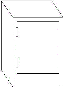
Normally-closed power distribution cabinet
A power distribution cabinet and normally closed technology, which is applied in the field of power distribution cabinets with lockable doors, can solve the problems of complex structure of the cabinet door locking device, complicated opening or closing of the cabinet door, and poor locking performance of the cabinet door. , to achieve the effect of simple structure, good locking performance and improved efficiency
- Summary
- Abstract
- Description
- Claims
- Application Information
AI Technical Summary
Problems solved by technology
Method used
Image
Examples
Embodiment 1
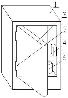
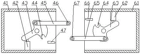
[0027] A normally closed power distribution cabinet, including a cabinet body 1 and a cabinet door 2, the cabinet body 1 and the cabinet door 2 are pivotally connected by a pivot device 3, so that the cabinet door 2 can rotate freely on the cabinet body 1, realizing the cabinet Opening or closing of door 2. The inner wall of the cabinet door 2 is connected with a first locking part 6, and the inner wall of the cabinet body 1 is connected with a second locking part 4, and the first locking part 6 is matched with the second locking part 4, The cabinet door 2 can be locked on the cabinet body 1 through the first locking component 6 and the second locking component 4 . The second locking part 4 includes a second lock body 41 fixedly connected to the cabinet body 1, a cavity is opened in the second lock body 41, and a second swinging part 43 is hinged in the cavity of the second lock body 41. , the second swing member 43 can rotate in the second lock body 41 . The inner chamber o...
Embodiment 2
[0032] On the basis of Embodiment 1, in order to facilitate the smooth introduction of the locking shaft on the connecting rod into the corresponding locking groove, a second lock body 41 is provided with a second lock body 41 on the side close to the second locking groove 44 Two guide blocks 47, when in the process of locking the cabinet door 2, the first connecting rod 65 moves to the side close to the second guide block 47, when the first connecting rod 65 moves to the second guide block 47, the second The guide block 47 can smoothly guide the first engaging shaft of the first connecting rod 65 into the second engaging groove 47 .
[0033] A first guide block 67 is provided on the side close to the first engagement groove 64 in the first lock body 61 , and when the cabinet door 2 is locked, the second connecting rod 45 moves toward a side close to the first guide block 67 . side movement, when the second connecting rod 45 moves to the first guiding block 67 , the first guid...
Embodiment 3
[0037] On the basis of the first or second embodiment, the reset mechanism includes a normally closed rope 54 , a normally closed spring 53 and a spring seat 51 . A first cavity 55 is provided in the pivoting ring 2, a second cavity 52 communicating with the first cavity 55 is provided on the left blade 1, and the fixed end of the normally closed rope 54 is fixedly connected to the first cavity 55. On the pivoting device 3, and part of the normally closed rope 54 is wound on the pivoting device 3 in the first cavity 55, and the free end of the normally closed rope 54 is wound on the pivoting device 3 and then penetrates into the second cavity 52, the free end of the normally closed rope 54 passes through the center of the normally closed spring 53 and is fixedly connected to the spring seat 51, the spring seat 51 is connected to the normally closed spring 53, and the other end of the normally closed spring 53 is pressed against the second cavity 52 bottom.
[0038] This reset...
PUM
 Abstract
Description
Claims
Application Information
 - R&D
- Intellectual Property
- Life Sciences
- Materials
- Tech Scout
- Unparalleled Data Quality
- Higher Quality Content
- 60% Fewer Hallucinations
Browse by: Latest US Patents, China's latest patents, Technical Efficacy Thesaurus, Application Domain, Technology Topic, Popular Technical Reports.
© 2025 PatSnap. All rights reserved.Legal|Privacy policy|Modern Slavery Act Transparency Statement|Sitemap|About US| Contact US: help@patsnap.com


