
A mesh networking method based on multi-channel optical fiber redundancy backup

A redundant backup and multi-channel optical fiber technology, which is applied in the field of communication, can solve the problems of long video transmission delay, network capacity and node number limitation, freeze and other problems, and achieve breakthrough capacity and node number limitation, flexible and simple networking, The effect of flexible networking

Active Publication Date: 2019-04-16
CHINA ELECTRONICS TECH GRP NO 7 RES INST
View PDF5 Cites 0 Cited by
  • Summary
  • Abstract
  • Description
  • Claims
  • Application Information

AI Technical Summary

Problems solved by technology

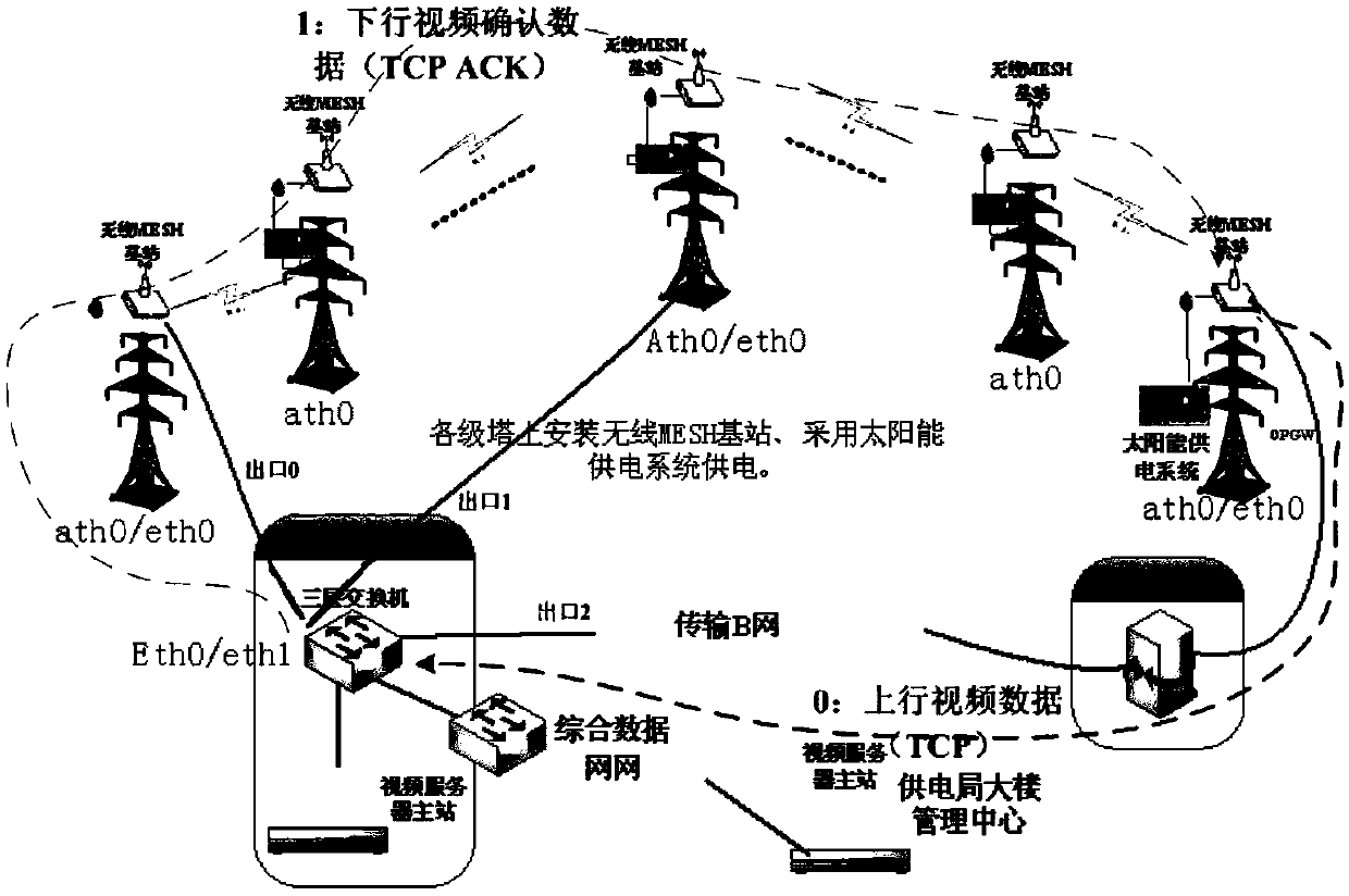
[0013] like figure 1 , for the downlink video acknowledgment data (TCP ACK) from the destination address to the aggregation root node of Suidong Station, because the OSPF of the aggregation root node cannot recognize the standard OLSR type external routing path and weight, the three-layer switch randomly selects the exit of Zengcheng Station As the next hop, the TCP ACK begins to detour through the multi-hop transmission of 13 sub-nodes from the aggregation root node of Zengcheng station to the aggregation root node of Suidong station. Due to the excessive number of hops, the attenuation of throughput is too large, resulting in video transmission Unable to watch high-definition video due to excessive delay
[0014] If a certain aggregation root node or optical fiber fails, the traffic passing through this root node cannot be automatically switched to another aggregation root node, and it is impossible to realize automatic redundant backup between multiple aggregation root nodes through optical fiber
[0015] Due to the bypass problem, the network capacity and the number of nodes are limited, which makes this scheme unable to be popularized and applied

Method used


Image

  • A mesh networking method based on multi-channel optical fiber redundancy backup
  • A mesh networking method based on multi-channel optical fiber redundancy backup
  • A mesh networking method based on multi-channel optical fiber redundancy backup

Examples


Embodiment 1

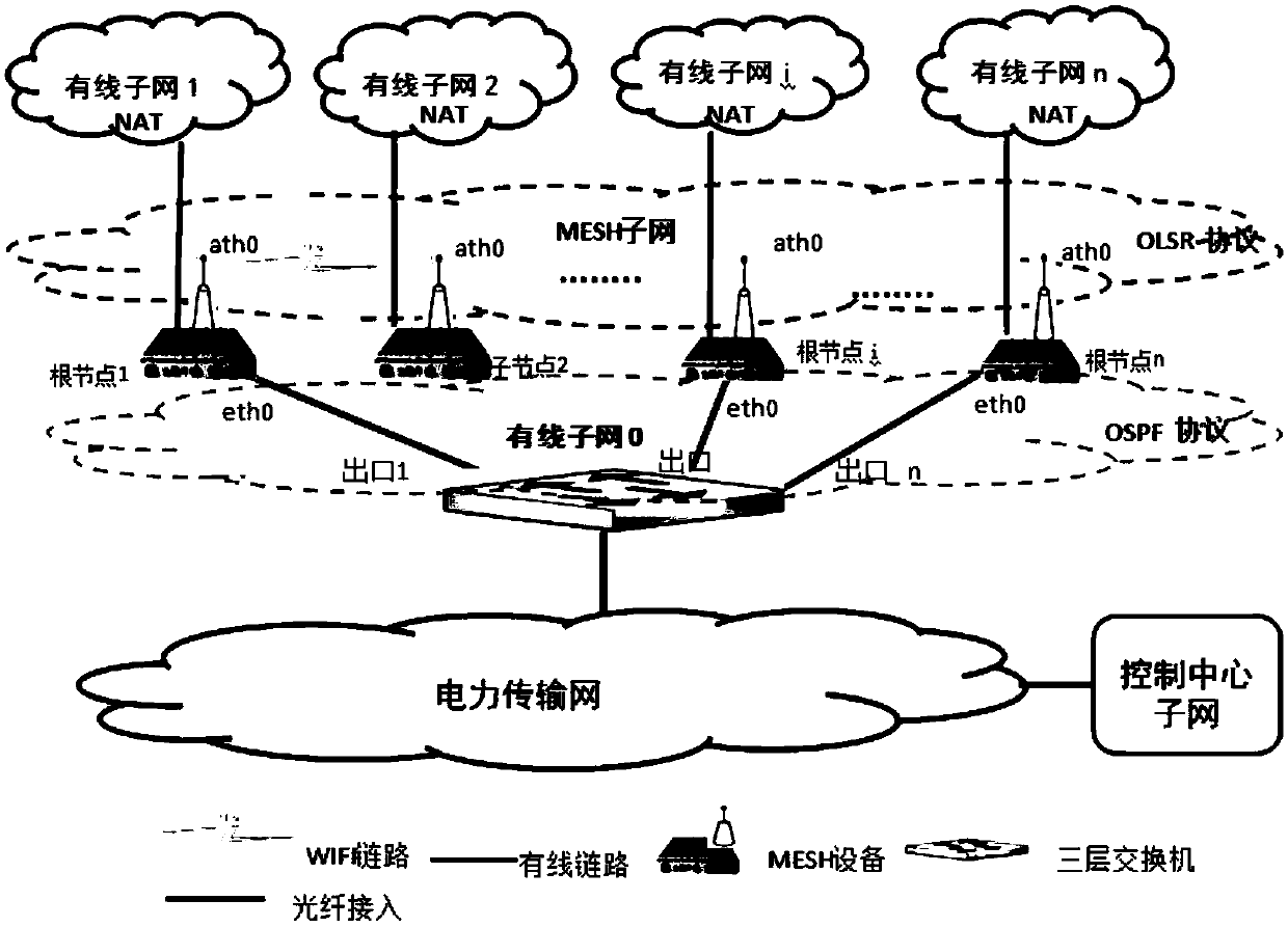
[0036] Aiming at the technical bottleneck of the existing MESH network, the present invention proposes a MESH networking method based on multi-channel optical fiber redundancy backup. The networking is as follows: figure 2 shown. The MESH networking node equipment is based on the IBSS mode of the 802.11 protocol, which is suitable for sensor data transmission and video data return, and can access the wireless service of line inspectors. The MESH node device has two radio frequency modules. The radio frequency module 1 works in the dual-antenna 5.8G frequency band and is used for wireless backhaul (between the wireless node and the gateway) service transmission. The backhaul channel is simultaneously composed of the receiving service (ingress) and the sending service ( egress) traffic sharing. The wireless radio frequency unit 2 works in the 2.4G frequency band AP mode, adopts AES encryption method, and is used to connect to the wireless client.

[0037] In this mode, the ga...


PUM


Abstract

The invention relates to a MESH networking method based on multi-channel optical fiber redundancy backup, which uses optical fibers to connect all aggregation root nodes in the MESH network with a three-layer switch, and determines the access point of the three-layer switch according to the network capacity of the MESH network. The number and location of the aggregation root node; among them, the child nodes under the aggregation root node run the H-OLSR dynamic routing protocol, and the H-OLSR dynamic routing protocol can select the optimal routing path to the aggregation root node based on the comprehensive index of energy and power as the judgment basis ;The three-layer switch runs the OSPF dynamic routing protocol; the aggregation root node runs the H-OLSR dynamic routing protocol and the OSPF dynamic routing protocol supporting the H-OLSR dynamic routing protocol, and the aggregation root node communicates with the child nodes through the H-OLSR dynamic routing protocol. The aggregation root node communicates with the Layer 3 switch through the OSPF dynamic routing protocol.

Description

technical field [0001] The invention relates to the technical field of communication, and more specifically, to a MESH networking method based on multi-channel optical fiber redundancy backup. Background technique [0002] The nodes in the MESH network are divided into aggregation root nodes and sub-nodes. The aggregation root node is connected to one or more sub-nodes. The traffic of all sub-nodes under the aggregation root node is forwarded to the corresponding aggregation root node through multiple hops, and then the aggregation The root node is connected to a Layer 3 switch or router. The aggregation root node and the child nodes under the aggregation root node belong to the same subnet. [0003] In traditional MESH network networking, there are mainly the following two solutions: [0004] Solution 1: A single aggregation root node is connected to a Layer 3 switch or router through optical fibers. [0005] This access method has great disadvantages. When the aggregati...

Claims


Application Information

Patent Timeline
Patent Type & Authority Patents(China)
IPC IPC(8): H04L12/713H04L12/721H04L45/586
CPCH04L45/12H04L45/124H04L45/22
Inventor 彭松林李新征曹叠马井泉陈玮思
Owner CHINA ELECTRONICS TECH GRP NO 7 RES INST
Learn More