Energy-saving air-seal pneumatic conveying pump

A pneumatic conveying and energy-saving technology, which is applied in the field of energy-saving air-sealed pneumatic conveying pumps, can solve the problems of affecting the conveying distance, fast wear of air lock, and high cost of use, so as to reduce the cost of use, avoid pressure backlash, and convey distance far effect

Active Publication Date: 2016-09-07
HUNAN HUIFENG ENVIRONMENTAL PROTECTION TECH DEV CO LTD
View PDF10 Cites 0 Cited by
  • Summary
  • Abstract
  • Description
  • Claims
  • Application Information

AI Technical Summary

Problems solved by technology

[0004] Jet-type pneumatic conveying pumps have high requirements on the material and processing accuracy of the air lock, the air lock wears quickly, the use cost is high, the air lock pressure is limited, which affects the conveying distance, and requires a certain amount of electric energy, which cannot give full play to the performance of the jet pump

Method used


Image

  • Energy-saving air-seal pneumatic conveying pump

Examples


Embodiment Construction

[0013] The present invention will be further described in detail below in conjunction with the accompanying drawings and specific embodiments.

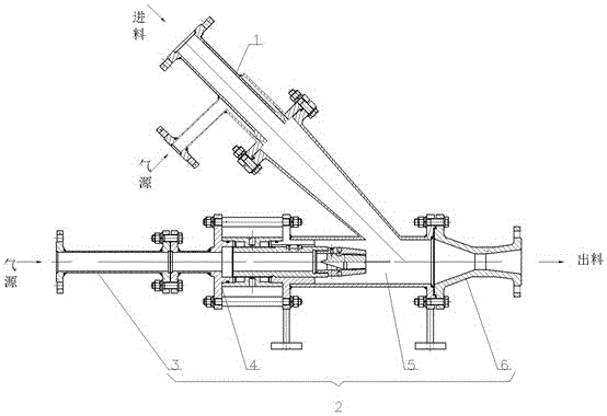
[0014] refer to figure 1 , the present embodiment comprises jet type pneumatic conveying pump 2, and jet type pneumatic conveying pump 2 comprises storage room 5, and one end of storage room 5 is provided with the gas source connection pipe 3 that communicates with storage room 5, and the other end is provided with storage room 5 and communicates with. Venturi tube 6; one side of the storage chamber 5 is provided with a nozzle 4, and the other side of the storage chamber 5 is provided with a gas-sealed jet 1 communicated with the storage chamber 5, and the gas-sealed jet 1 is located at the side of the storage chamber 5 above. The centerline of the air-sealed ejector 1 forms an included angle of 45° with the centerline of the jet pneumatic conveying pump 2 . The gas-sealed ejector 1 is made of ordinary Q235 steel.

[0015] The gas-...


PUM


Abstract

An energy-saving air-seal pneumatic conveying pump comprises a jet pneumatic conveying pump. The jet pneumatic conveying pump comprises an accommodating chamber. An air source connecting pipe communicated with the accommodating chamber is arranged at one end of the accommodating chamber. A Venturi communicated with the accommodating chamber is arranged at the other end of the accommodating chamber. A nozzle is arranged on one side of the accommodating chamber. An air-seal jet device communicated with the accommodating chamber is arranged on the other side of the accommodating chamber. The air-seal jet device is positioned above the accommodating chamber. The energy-saving air-seal pneumatic conveying pump integrates the technology principles of negative-pressure jetting, positive-pressure air locking and Venturi jetting, the continuous conveying of powdery materials and granular materials is realized, the materials are sufficiently mixed with gas sufficiently under the action of the air-seal jet device before entering the accommodating chamber, and the materials are fluidified to enable the jet pneumatic conveying pump to operate in a more efficient and energy-saving manner; the materials enter the accommodating chamber under a certain of pressure through the air-seal jet device, so as to prevent pressure hysteresis effectively; and the air-seal jet device can replace a mechanical air locking device, so that the using cost can be effectively reduced.

Description

technical field [0001] The invention relates to an energy-saving air-sealed pneumatic conveying pump. Background technique [0002] Pipeline pneumatic conveying is a common conveying method in the field of industrial material conveying. In the continuous pneumatic conveying system, the pneumatic conveying pump is a common conveying device. [0003] Most of the existing pneumatic conveying pumps are jet-type pneumatic conveying pumps. In order to ensure continuous conveying, it is necessary to install an air lock (feeder) at the upper end of the storage room. When the pressure range enters another pressure range, air channeling occurs to maintain the smooth circulation of powdery or granular materials. [0004] Jet-type pneumatic conveying pumps have high requirements on the material and machining accuracy of the airlock, the airlock wears quickly, the cost of use is high, the airlock pressure is limited, affects the conveying distance, and requires a certain amount of elect...

Claims


Application Information

Patent Timeline
IPC IPC(8): B65G53/50
CPCB65G53/50
Inventor 郑德明常熹钰王征和邱伟
Owner HUNAN HUIFENG ENVIRONMENTAL PROTECTION TECH DEV CO LTD
Why Eureka
Try Eureka