Engine intake manifold with cooler inside and high tightness

A technology of intake manifold and cooler, which is applied in the direction of machines/engines, internal combustion piston engines, engine components, etc., and can solve the problems of not fully utilizing the heat exchange function of the cooler, too many sealing parts, and large sealing surface. Achieve the effect of light weight, high heat exchange efficiency and small sealing surface

Active Publication Date: 2016-09-07
索格菲(苏州)汽车部件有限公司
View PDF4 Cites 2 Cited by
  • Summary
  • Abstract
  • Description
  • Claims
  • Application Information

AI Technical Summary

Problems solved by technology

[0005] The purpose of the present invention is to provide an engine intake manifold with a built-in cooler and high sealing performance, so as to solve the problems of the prior art that the sealing surface is too large, the structure is complicated due to too many sealing parts, and the heat exchange function of the cooler cannot be fully utilized. The problem

Method used


Image

  • Engine intake manifold with cooler inside and high tightness
  • Engine intake manifold with cooler inside and high tightness
  • Engine intake manifold with cooler inside and high tightness

Examples


Embodiment

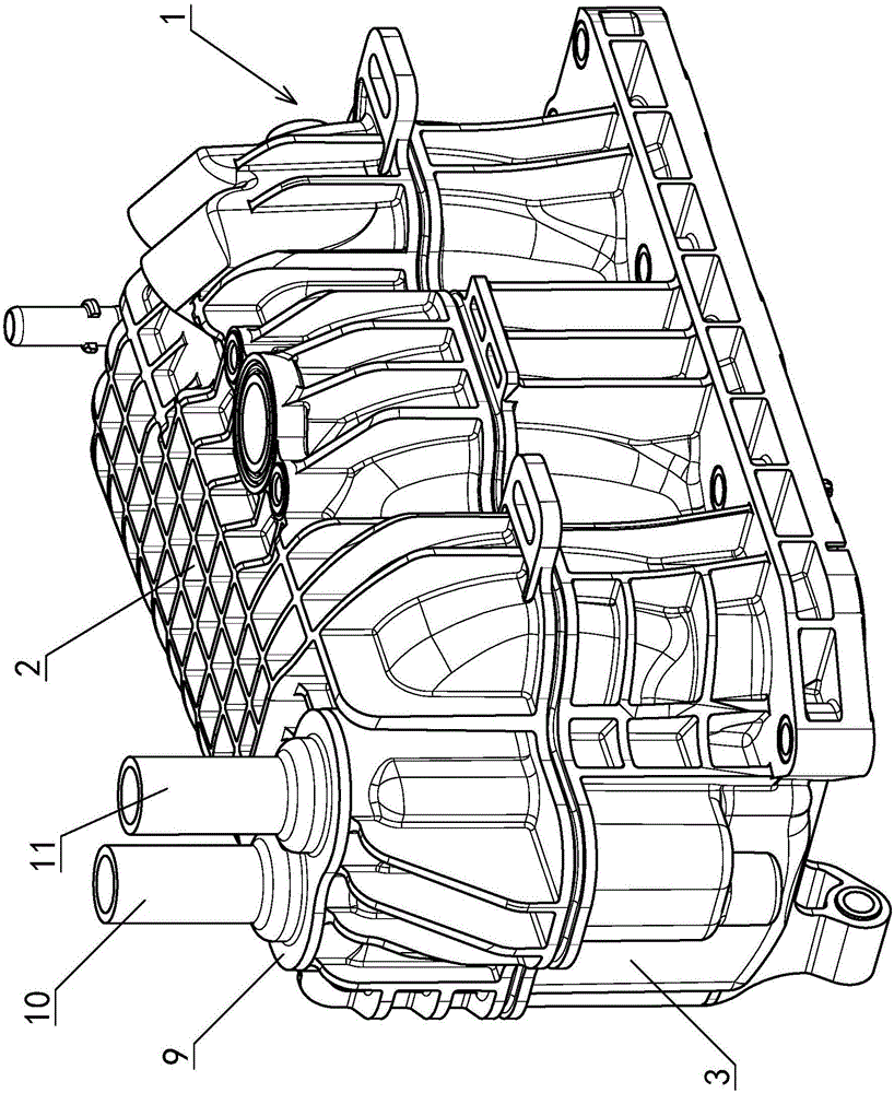
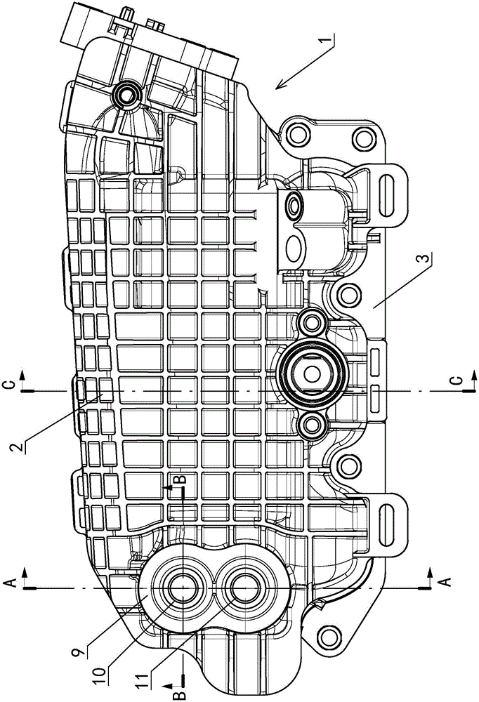
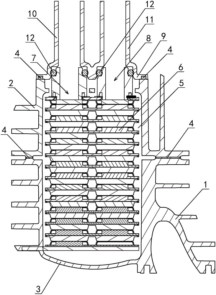
[0025] Example: see attached Figure 1~5 As shown, an engine intake manifold with a built-in cooler and high sealing performance has a casing 1, which includes an upper casing 2 and a lower casing 3; the upper casing 2 and the The lower casing 3 is connected by a welding structure 4, forming an assembly chamber 5 formed between the two, the assembly chamber 5 is used for the assembly and accommodation of the cooler 6, and the cooler 6 connects the assembly chamber 5 Separated into two independent air chambers; the cooler 6 includes a water inlet 7 and a water outlet 8 for cooling liquid, and the water inlet 7 and the water outlet 8 protrude from the upper casing 2; the cooling The interior of the device 6 is provided with a coolant flow channel (not shown in the figure) that communicates with the water inlet 7 and the water outlet 8 .

[0026] The casing 1 also includes a coolant guide cover 9, which is covered on the upper casing 2 and is sealed and connected with the upper ...


PUM


Abstract

The invention discloses an engine intake manifold with a cooler inside and high tightness. The engine intake manifold has a shell, and is characterized in that the shell includes an upper cover, a lower cover and a cooling liquid guide cover; the upper cover and the lower cover are connected through a sealing structure to form an assembly cavity therebetween; the assembly cavity is used for assembling and accommodating the cooler; the cooler divides the assembly cavity into two independent gas chambers; the cooling liquid guide cover covers the shell, and is tightly connected with the shell to form a closed gas chamber between the cooling liquid guide cover and the cooler in the shell; the cooling liquid guide cover is provided with a cooling liquid lead-in pipe and a cooling liquid lead-out pipe corresponding to a water inlet and a water outlet of the cooler; the cooling liquid lead-in pipe is tightly connected with the water inlet; and the cooling liquid lead-out pipe is tightly connected with the water outlet. The engine intake manifold has the advantages of simple structure, good sealing effect, high heat exchange efficiency, small size and light weight.

Description

technical field [0001] The invention relates to an engine component, in particular to a high-tightness engine intake manifold, which has a built-in cooler and can lead and export cooling liquid. Background technique [0002] Generally, the function of the intake manifold equipped with a cooler in the engine is to cool the high-temperature air to a predetermined temperature range after passing through the cooler. Its design principle is to place a finned cooler in the middle of the inner cavity of the intake manifold, and divide the cavity into two independent air chambers. The hot air of the intake manifold flows through the cooler from the first air chamber, and passes through The cooling fins that contact the cooler lower the temperature, and the cooled air enters another air chamber. There is coolant flowing inside the cooler, which takes away the heat from the cooling fins and keeps the cooler at a lower temperature, thereby ensuring that the hot air can be continuously...

Claims


Application Information

Patent Timeline
Patent Type & Authority Applications(China)
IPC IPC(8): F02M35/104F02M35/10F02B29/04
CPCF02B29/0437F02B29/0462F02M35/10091F02M35/10268F02M35/104Y02T10/12
Inventor 沃德里·吉恩·保尔徐海锋孙大海
Owner 索格菲(苏州)汽车部件有限公司
Why Eureka
Try Eureka