Vacuum arc extinguishing chamber transferring and conveying disk

A technology of vacuum interrupter and conveying tray, which is applied in the direction of conveyor objects, transportation and packaging, etc., can solve the problems of daily management difficulties, achieve the effects of convenient daily management, reduce production costs, and improve economic benefits

Active Publication Date: 2016-09-14
BEIJING AOPU KEXING TECH
View PDF5 Cites 4 Cited by
  • Summary
  • Abstract
  • Description
  • Claims
  • Application Information

AI Technical Summary

Problems solved by technology

[0002] The vacuum interrupter is the core component of the medium and high voltage power switch. It has a wide variety of specifications. At present, most of the transfer trays of the vacuum interrupter transmission line are non-adjustable, which requires each interrupter to be equipped with a transfer tray. As a result, there are many types of transfer trays and difficulties in daily management.

Method used


Image

  • Vacuum arc extinguishing chamber transferring and conveying disk
  • Vacuum arc extinguishing chamber transferring and conveying disk
  • Vacuum arc extinguishing chamber transferring and conveying disk

Examples


Embodiment 1

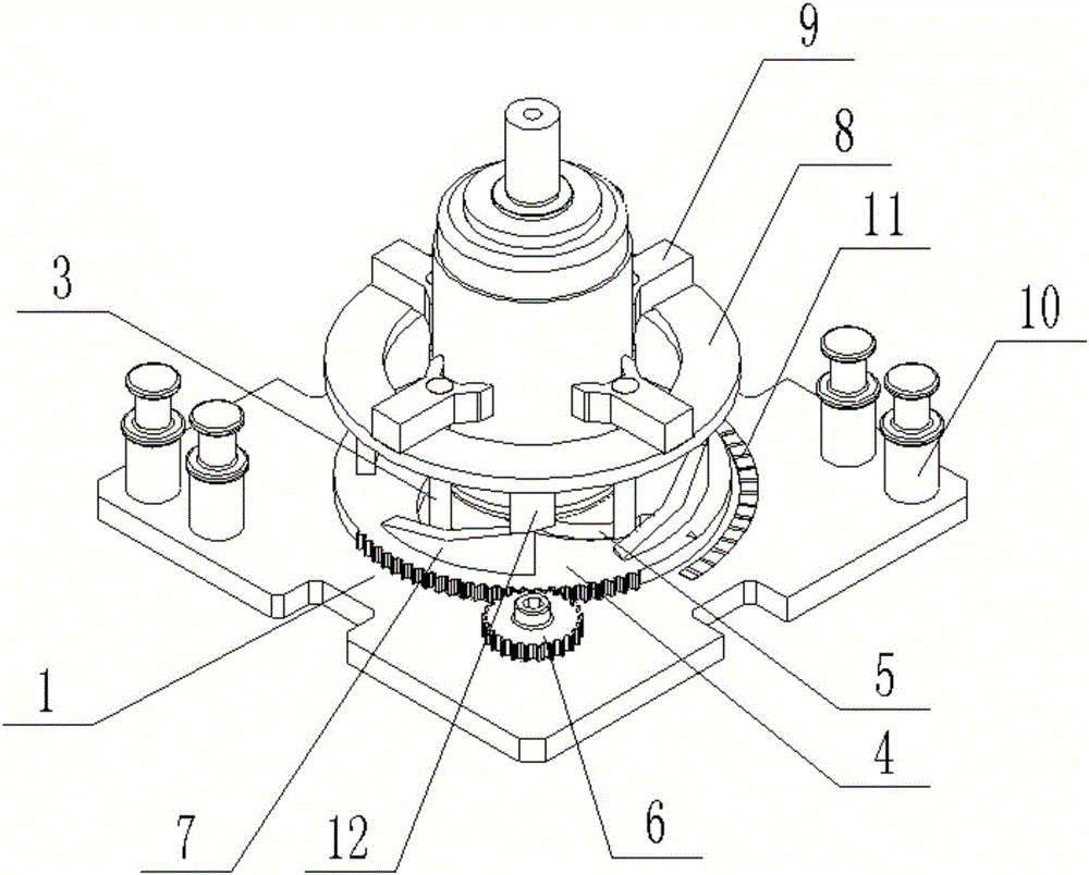
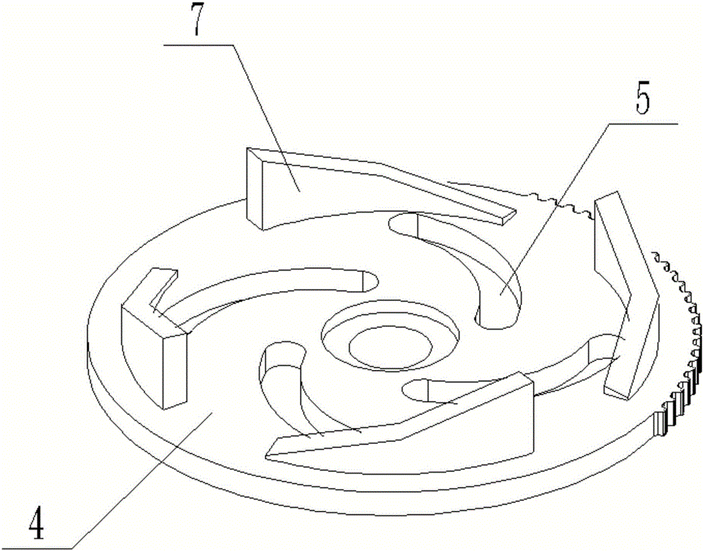
[0024] Example one: such as Figure 1-3 As shown, a vacuum interrupter transfer tray according to an embodiment of the present invention includes a transfer tray base 1, and a cross-shaped guide rod sliding groove 2 is provided on the transfer tray base 1, and the guide The rod sliding groove 2 is slidably connected with a retractable guide rod 3, the transfer disc base 1 is movably connected with an adjustment disc 4, and the adjustment disc 4 is provided with a curve corresponding to the guide rod sliding groove 2 The chute 5, the edge of the adjusting plate 4 is movably connected with an adjusting wheel 6 arranged on the transfer plate base 1, and the adjusting plate 4 is provided with a plurality of upwardly bulging lifting slides 7, and the lifting The slideway 7 is slidably connected to the second adjusting plate 8, and the second adjusting plate 8 is slidably connected with a clamping claw 9 corresponding to the vacuum interrupter, and the clamping claw 9 is fixedly conn...

Embodiment 2

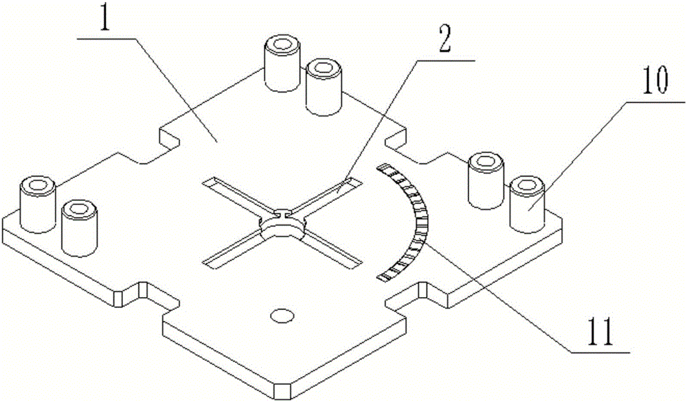
[0030] Embodiment two: such as Figure 4 As shown, a vacuum interrupter transfer tray according to an embodiment of the present invention includes a transfer tray base 1 provided with a detection fixture seat 10 and a cross-shaped guide rod sliding groove 2 And an arc-shaped ruler 11, the guide rod sliding groove 2 is slidably connected with a guide rod 3, and the guide rod 3 is a nylon limit rod for clamping the vacuum interrupter. The transfer tray base 1 is movable An adjustment disc 4 is connected, and the adjustment disc 4 is provided with a curved sliding groove 5 corresponding to the guide rod sliding groove 2, and the adjustment disc 4 is provided with a pointer corresponding to the scale 11.

[0031] In specific use, first rotate the adjustment plate 4, and the adjustment plate 4 drives the curved slide groove 5 to rotate. The curved slide groove 5 pushes the guide rod 3 to move back and forth in the guide rod slide groove 2, thereby controlling the clamping of the guide ...


PUM


Abstract

The invention relates to a vacuum arc extinguishing chamber transferring and conveying disk comprising a transferring disk base. A cross-shaped guiding rod sliding groove is formed in the transferring disk base and is connected with telescopic guiding rods in a sliding manner; a first adjusting disk is movably connected to the transferring disk base and provided with a curve sliding groove corresponding to the guiding rod sliding groove; an adjusting wheel is movably connected to the edge of the first adjusting disk and movably connected to the transferring disk base; a plurality of lifting slide ways protruding upwards are arranged on the first adjusting disk and connected with a second adjusting disk in a sliding manner; and the second adjusting disk is connected with clamping jaws corresponding to a vacuum arc extinguishing chamber, and the clamping jaws are fixedly connected with the guiding rods.

Description

Technical field [0001] The present invention relates to the technical field of vacuum interrupter detection, in particular to a vacuum interrupter transfer tray. Background technique [0002] The vacuum interrupter is the core component of the medium and high voltage power switch. There are many types of specifications. At present, the transfer tray of the vacuum interrupter transmission line is mostly non-adjustable, which causes each interrupter to be equipped with a transfer tray. As a result, problems such as a wide variety of transfer trays and difficulty in daily management have been caused. [0003] Therefore, the development of a transfer tray that can adapt to different specifications of arc extinguishing chambers has become an urgent problem for the industry. Summary of the invention [0004] The present invention proposes a vacuum interrupter transfer tray, which overcomes the above-mentioned shortcomings in existing products. [0005] The purpose of the present invention...

Claims


Application Information

Patent Timeline
Patent Type & Authority Applications(China)
IPC IPC(8): B65G47/74
CPCB65G47/74
Inventor 赵宝星薛道荣
Owner BEIJING AOPU KEXING TECH
Why Eureka
Try Eureka