Process for Producing Molten Iron and Apparatus Therefor

Inactive Publication Date: 2007-12-27
KOBE STEEL LTD
View PDF2 Cites 36 Cited by
  • Summary
  • Abstract
  • Description
  • Claims
  • Application Information

AI Technical Summary

Benefits of technology

[0012] According to the present invention, the hearth can be more securely protected by using the bedding carbonaceous material to avoid troubles such as the peeling of the hearth. Therefore, the moving hearth type reducing furnace can be continuously operated over a longer period of time. Further, since the char after devolatization contains no volatile content, the damage of the refractory by the combustion of the volatile content in the iron-melting furnace can be prevented, thereby extending the lift of the refractory of the i

Problems solved by technology

However, only qualitative actions and effects were indicated concerning the method using the bedding carbonaceous material, and specific operating conditions for further reducing the fuel specific consumption while stabilizing the operations of the rotary hearth furnace and the melting furnace were still uncertain.
However, the above process includes no melting furnace and produces the met

Method used


Image

  • Process for Producing Molten Iron and Apparatus Therefor
  • Process for Producing Molten Iron and Apparatus Therefor
  • Process for Producing Molten Iron and Apparatus Therefor

Examples


first embodiment

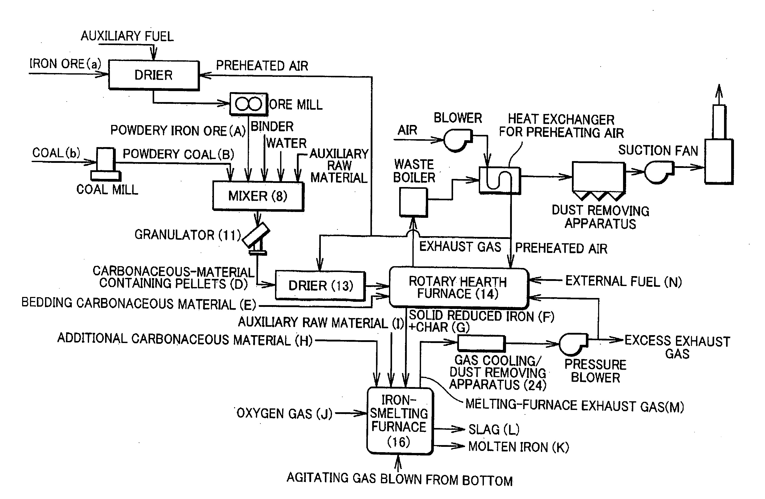
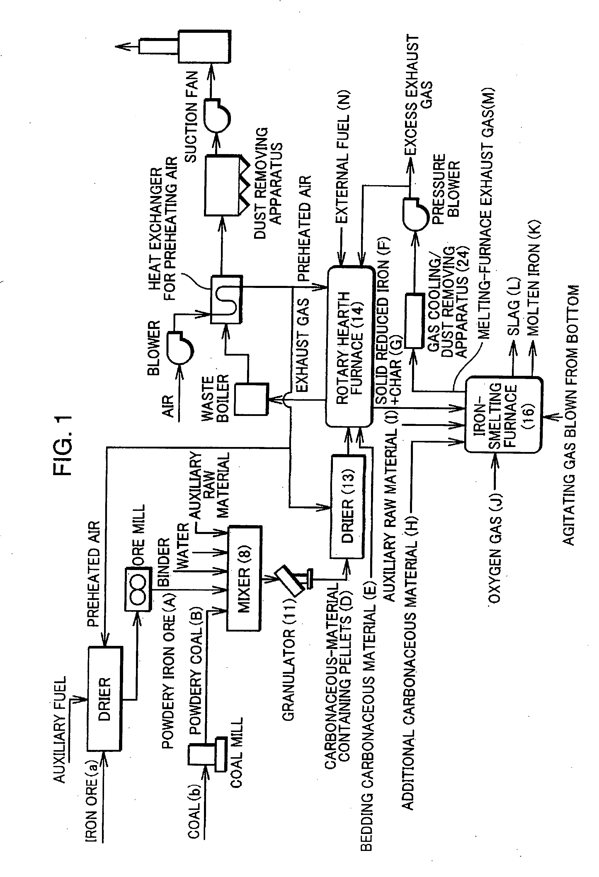
[0024]FIG. 1 is a flow diagram of a molten iron production process showing one embodiment of the present invention, wherein this molten iron production process is constructed by coupling a rotary hearth furnace 14 as a moving hearth type reducing furnace and an iron-melting furnace 16.

[0025] Iron ore “a” as an iron oxide source and coal b as a carbonaceous reducing agent are, if necessary, separately crushed into particles having diameters of approximately below 1 mm. The thus obtained powdery iron ore A as a powdery iron oxide source and powdery coal B as a powdery carbonaceous reducing agent are mixed at a specified ratio, a suitable amount of binder and / or a suitable amount of moisture are added if necessary (further, all or a part of an auxiliary raw material I as a slag forming agent to be added in the iron-melting furnace 16 may be added here), and these are mixed by a mixer 8. Thereafter, the mixed compound is granulated to have a particle diameter of about 6 to 20 mm in a g...

second embodiment

[0064] The following step (6) may be provided between the reduction step (the above step (2)) and the melting furnace charging step (the above step (3)).

[0065] (6) Step of Hot-Forming the Solid Reduced Iron F and the Char G Together while they are Hot

[0066] Specifically, the solid reduced iron F and the char G may be dispensed together, for example, from the hopper 106 while being hot, and pressure-formed into hot briquetted iron (HBI) by a hot forming machine, and this HBI may be dropped and charged into the iron-melting furnace 16 at a temperature of, e.g. 500 to 1100° C. without being cooled.

[0067] This prevents the fine particles from scattering at the time of being charged into the iron-melting furnace 16, and an amount of dust in the exhaust gas from the iron-melting furnace 16 can be considerably reduced. Therefore, an iron yield and a carbon yield can be considerably improved.

[0068] Since the purpose of forming here is to eliminate fine particles, the shape of the compac...

third embodiment

[0069] The following steps (7) to (9) may be provided instead of the melting furnace charging step (the above step (3)).

[0070] (7) Hot-classifying step of classifying the solid reduced iron F and the char G into coarse particles and fine particles while they are hot or without being substantially cooled after the solid reduced iron F and the char G are taken together out of the rotary hearth furnace 14.

[0071] (8) Coarse particle charging step of gravitationally charging coarse particles into the iron-melting furnace 16

[0072] (9) Fine particle injection step of charging the fine particles into the iron-melting furnace 16 by injection

[0073] Specifically, facilities having the following construction may be employed. A screen having sieve meshes of about 2 to 5 mm is provided at a portion of the rotary hearth furnace 14 where the solid reduced iron F and the char G are discharged, and the solid reduced iron F and the char G are sieved while being hot, wherein course particles above t...


PUM

PropertyMeasurementUnit
Temperatureaaaaaaaaaa

Abstract

A bedding carbonaceous material is charged onto a hearth of a rotary hearth furnace, carbonaceous-material containing pellets containing powdery iron ore and powdery coal are placed on the bedding carbonaceous material, and the hearth is caused to pass inside the rotary hearth furnace to heat and reduce the carbonaceous-material containing pellets to solid reduced iron and to heat and dry the bedding carbonaceous material by distillation into char. Subsequently, the solid reduced iron and the char are charged into an iron-melting furnace without being substantially cooled, and an oxygen gas is blown into the iron-melting furnace to melt the solid reduced iron, thereby obtaining molten iron. At least a part of an exhaust gas from the iron-melting furnace is used as a fuel gas for the rotary hearth furnace after being cooled and having dust removed.

Description

TECHNICAL FIELD [0001] The present invention relates to a method and an apparatus for producing molten iron and particularly to an improved method for efficiently producing molten iron having a high iron purity by heating and reducing an iron oxide source such as iron ore together with a carbonaceous reducing agent such as coal in a molten iron production process constructed by combining a moving hearth type reducing furnace and an iron melting furnace. BACKGROUND TECHNOLOGY [0002] The inventors of the present invention developed a molten iron production method for, in a molten iron production process in which a rotary hearth furnace (moving hearth type reduction furnace) and a melting furnace (iron-melting furnace) are coupled, obtaining molten iron by feeding solid reduced iron to a melting furnace after heating and reducing a compact containing iron oxide and a carbonaceous reducing agent to the solid reduced iron having a metallization degree of 60% or higher in a rotary hearth ...

Claims


Application Information

Patent Timeline
IPC IPC(8): C21B13/10
CPCC21B13/0066C21B13/0086C22B5/10C21B13/143C22B1/245C21B13/105C21B2100/44C21B2100/66Y02P10/134Y02P10/20C21B11/00
Inventor TANAKA, HIDETOSHIMIMURA, TSUYOSHIHARADA, TAKAOHAJIKA, KIMINORIYASO, TADASHIKURAKAKE, TOSHIYUKI
Owner KOBE STEEL LTD
Why Eureka
Try Eureka