High-sensitivity tooth bar load measurement apparatus based on annular grooves

A high-sensitivity, load-measuring technology that is applied to measuring devices, measuring forces, instruments, etc., and can solve problems such as technical infeasibility, infeasibility, and inaccurate load values

Inactive Publication Date: 2016-09-14
KEEN OFFSHORE ENG CO LTD
View PDF6 Cites 0 Cited by
  • Summary
  • Abstract
  • Description
  • Claims
  • Application Information

AI Technical Summary

Problems solved by technology

[0004] 1) Through the measurement of physical quantities such as hydraulic cylinder pressure and motor power, the load on the gear and rack of the gearbox of the offshore platform lifting unit is indirectly calculated through theoretical conversion; this method is an indirect measurement, but due to the system lag and energy Loss, and factors such as friction, energy loss, and installation system errors that cannot be eliminated in each link of the entire transmission chain, the load value measured by the relevant measuring device is very inaccurate
[0005] 2) On the other hand, the load is measured by installing strain gauges on the gears and racks, or installing load sensors on the existing gear and rack connection structures; these two methods are direct measurements, and the installation of strain gauges is used. The method is limited to the working process and working conditions of the gearbox, and the strain gauge cannot be installed, which is technically not feasible
Using the method of adding a load sensor requires a relatively large structural modification of the connection structure of the unit gearbox, which is also not feasible

Method used


Image

  • High-sensitivity tooth bar load measurement apparatus based on annular grooves
  • High-sensitivity tooth bar load measurement apparatus based on annular grooves
  • High-sensitivity tooth bar load measurement apparatus based on annular grooves

Examples


Embodiment Construction

[0031] The technical solutions of the present invention will be further described below in conjunction with the accompanying drawings and through specific implementation methods.

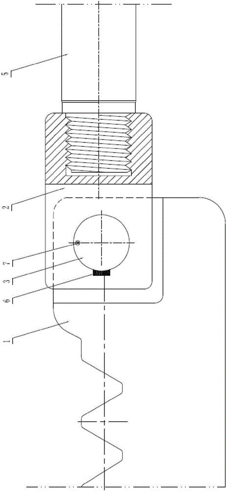
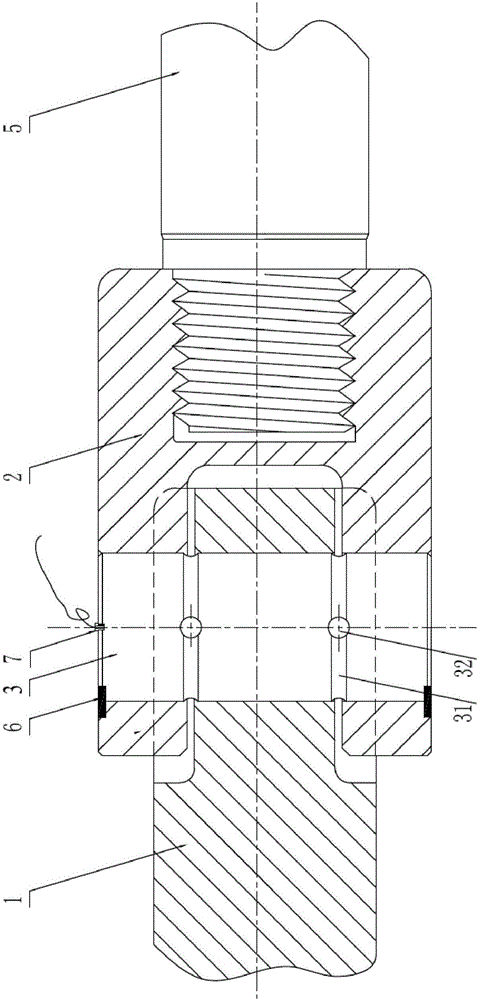
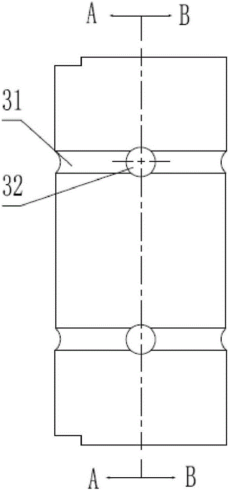
[0032] Such as Figure 1 to Figure 2 As shown, a high-sensitivity rack load measuring device based on an annular groove includes a rack 1 and a measuring device, and the measuring device includes a connector 2, a sensor elastic body 3 and a sensor;

[0033] The sensor elastic body 3 is a cylindrical structure, passing through and installed in the holes corresponding to the rack 1 and the connector 2, so that the rack 1 is installed on the connector 2;

[0034] The sensor is installed on the sensor elastic body 3 and arranged at the corresponding position of the contact surface between the rack 1 and the connecting part 2 to measure the force between the rack 1 and the connecting part 2 .

[0035] The elastic body 3 of the sensor is located at the corresponding position on the contact surface betwee...


PUM


Abstract

The invention relates to the field of a sea elevating platform, and specifically relates to a high-sensitivity tooth bar load measurement apparatus based on annular grooves. The apparatus comprises a tooth bar and a measurement device, and the measurement device comprises a connecting piece, a sensor elastomer and sensors; the sensor elastomer is of a cylindrical structure, passes through and is installed in a hole corresponding to the tooth bar and the connecting piece, and the tooth bar is enabled to be installed to the connecting piece; the sensors are installed on the sensor elastomer and are arranged at corresponding positions of a contact surface between the tooth bar and the connecting piece, a stress condition between the tooth bar and the connecting piece is measured, the sensor elastomer is radially provided with the two annular grooves and is arranged at a position of the contact surface between the tooth bar and the connecting piece, and the sensors are installed in the annular grooves. Through such a structure, integrated installation of the tooth bar is realized by use of the sensor elastomer, the connecting piece and a chuck; and through the sensors stuck in the sensor elastomer and wiring terminals for input and output of installation signals, direct measurement of a tooth bar load of a maritime work elevating unit gear case is realized.

Description

technical field [0001] The invention relates to the field of marine lifting platforms, in particular to a high-sensitivity rack load measuring device based on an annular groove. Background technique [0002] The large-load gear and rack drive unit is the key functional module to realize the lifting and lowering of offshore platform equipment. Due to the large load and uneven load distribution during the working process of the platform, and the multi-stage gear transmission in the power-load conversion process of the various functional components of the transmission chain Due to the change of physical parameters and other reasons, there are different degrees of safety risks in the existing lifting units. The current test methods cannot effectively and completely directly test the load, resulting in the lack of structural optimization and transformation of the existing offshore lifting units. Direct guidance data. [0003] At present, there is no direct measuring device for t...

Claims


Application Information

Patent Timeline
Patent Type & Authority Applications(China)
IPC IPC(8): G01L1/00
CPCG01L1/00
Inventor 马振军吴平平李光远陆军张静波
Owner KEEN OFFSHORE ENG CO LTD
Why Eureka
Try Eureka