Overhead power transmission line wire jumper hooking cable clamp semi-automatic replacement method

A technology of overhead transmission line and replacement method, applied in the field of semi-automatic replacement of overhead transmission line jumpers and hook clips, can solve problems such as unfavorable power grid stability, unsatisfactory combination gaps, damage, etc., to improve work efficiency and safety, promote The development of live work, the effect of simple and convenient operation

Active Publication Date: 2018-08-03
QUANZHOU POWER SUPPLY COMPANY OF STATE GRID FUJIAN ELECTRIC POWER
View PDF11 Cites 0 Cited by
  • Summary
  • Abstract
  • Description
  • Claims
  • Application Information

AI Technical Summary

Problems solved by technology

However, as the line is affected by natural environments such as wind, rain, oxidation, etc. during operation, defects such as loosening of the clamp bolts or serious oxidation or even fracture and damage often occur, resulting in heat, whipping, damage, and serious Serious accidents that can even lead to jumper breaks
[0003] Take the 220kV line as an example (the distance of the 110kV line is even narrower): Since the distance between the cross-arms of the tension pole tower is generally about 3 meters, and the sag of the jumper is generally about 2.2 meters, this will cause people to directly enter it for equipotential work. , deducting the space occupied by the human body, the combined gap between it and the live jumper and the cross-arm of the tower cannot meet the 2.1 meters, or the safety distance requirement of 1.8 meters cannot be met with the ground potential body such as the cross-arm of the tower when the jumper is overhauled, so For the replacement of the jumper and the hook clip, the method of power-off maintenance is generally adopted.
This is not conducive to the stability of the power grid, and secondly, it will cause a huge loss of power supply

Method used


Image

  • Overhead power transmission line wire jumper hooking cable clamp semi-automatic replacement method
  • Overhead power transmission line wire jumper hooking cable clamp semi-automatic replacement method
  • Overhead power transmission line wire jumper hooking cable clamp semi-automatic replacement method

Examples


Embodiment 1

[0045] A method for semi-automatically replacing wire jumpers and hook clamps of overhead transmission lines, providing a replacement tool, including an elastic fixing device 1 for parallel hook clamps, a spring clamp 2 for cover plates of parallel hook clamps, a remote electric operation wrench, and a magnetic suction type sleeve 3;

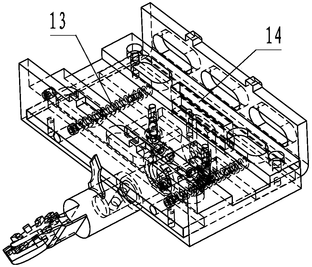
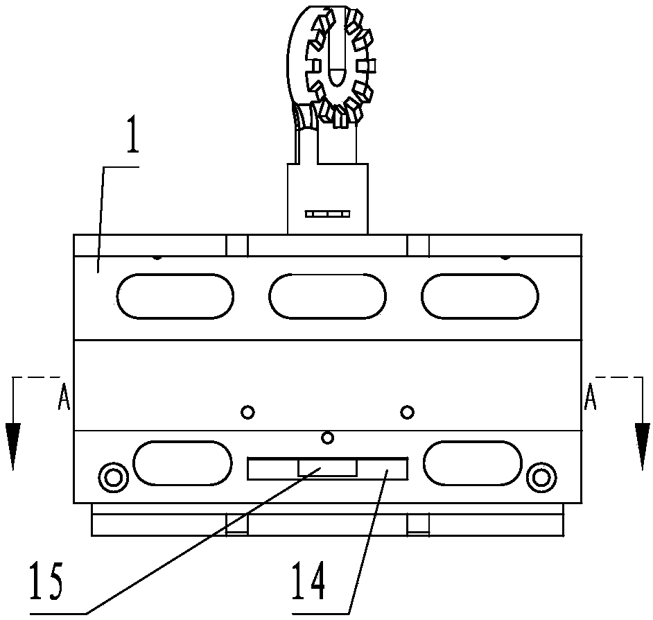
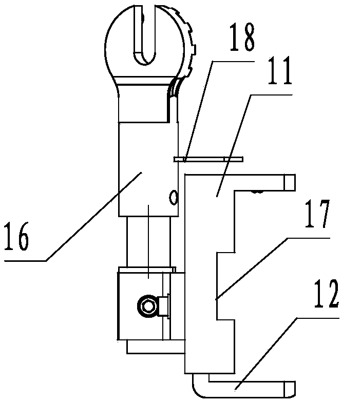
[0046]The elastic fixing device for hooking wire clips includes an L-shaped bottom plate 11 and an L-shaped splint 12, the L-shaped bottom plate and the splint are relatively set up to form a U-shaped groove structure, and the L-shaped bottom plate and the L-shaped splint are Arranged along the width direction of the U-shaped groove, the bottom edge of the bottom plate is a sandwich structure, and the bottom edge of the splint is inserted into the interlayer of the bottom edge of the bottom plate. The width of the bottom edge of the splint is smaller than the width of the bottom edge of the bottom plate. The sides are connected by spring 13, and...


PUM


Abstract

The invention discloses an overhead power transmission line wire jumper hooking cable clamp semi-automatic replacement method and provides an overhead power transmission line wire jumper hooking cableclamp semi-automatic replacement tool. The tool includes a hooking cable clamp elastic fixing device, a hooking cable clamp cover plate spring fixture, a remote electric operation wrench and a magnetic sleeve. The hooking cable clamp elastic fixing device and the hooking cable clamp cover plate spring fixture are utilized to place a hooking cable clamp onto a wire, and then the magnetic sleeve and the electric wrench are utilized for tightening. The replacement method is highly integrated in operation procedures, semi-automation is achieved on the basis of simple manual operation, the operation is simple and convenient, and a traditional operation method in which staff need to directly touch wire jumpers after the electric potential is equal or the electricity is cut off is changed; the operation efficiency and safety are greatly improved, and the development of lived operation is boosted.

Description

technical field [0001] The invention relates to a method for replacing parallel hooking wires, in particular to a semi-automatic replacement method for overhead power transmission line jumper parallel hooking wire clips. Background technique [0002] Overhead high-voltage transmission lines are an important part of the power grid. At present, 220kV transmission lines generally use double-split conductors, and the electrical connection of the tension-resistant towers generally adopts double jumpers. The double jumpers use hook clips to fix the two jumpers to prevent Whip each other or swing greatly, and at the same time, some 110kV line jumpers are used for passing the remaining material of the wires and hooking the clips and connecting them. However, as the line is affected by natural environments such as wind, rain, oxidation, etc. during operation, defects such as loosening of the clamp bolts or serious oxidation or even fracture and damage often occur, resulting in heat, ...

Claims


Application Information

Patent Timeline
Patent Type & Authority Applications(China)
IPC IPC(8): H02G1/02
CPCH02G1/02
Inventor 罗国档陈永红吴志成杨昌加庄宏彬吴玉婷陈宇昆赖丽萍王海波高领军钟松树林雅斯
Owner QUANZHOU POWER SUPPLY COMPANY OF STATE GRID FUJIAN ELECTRIC POWER
Why Eureka
Try Eureka