Low-Cost, Low-Power Lighting Systems and Lamp Assemblies

A lamp component and frequency technology, applied in the electronic field, can solve problems such as high cost

Active Publication Date: 2019-06-25
SIGNIFY HLDG BV
View PDF5 Cites 0 Cited by
  • Summary
  • Abstract
  • Description
  • Claims
  • Application Information

AI Technical Summary

Problems solved by technology

However, this solution is often costly, requiring a bulb assembly with complex analog and digital circuitry to perform the conversion of the AC supply waveform to a DC waveform typically required by low power lamps, including LED lamps.

Method used


Image

  • Low-Cost, Low-Power Lighting Systems and Lamp Assemblies
  • Low-Cost, Low-Power Lighting Systems and Lamp Assemblies
  • Low-Cost, Low-Power Lighting Systems and Lamp Assemblies

Examples


Embodiment Construction

[0032] Figure 5 An example lighting system 500 including a modulator 522 for providing compatibility between a low power lamp assembly 532 and other components of the lighting system is illustrated, according to an embodiment of the disclosure. like Figure 5 As shown, a lighting system 500 may include a voltage supply 504 , a dimmer 502 , a modulator 522 , and a plurality of lamp assemblies 532 . The voltage supply 504 can generate a supply voltage V SUPPLY , supply voltage V SUPPLY For example a nominal 60Hz / 110V line voltage in the US or a nominal 50Hz / 220V line voltage in Europe.

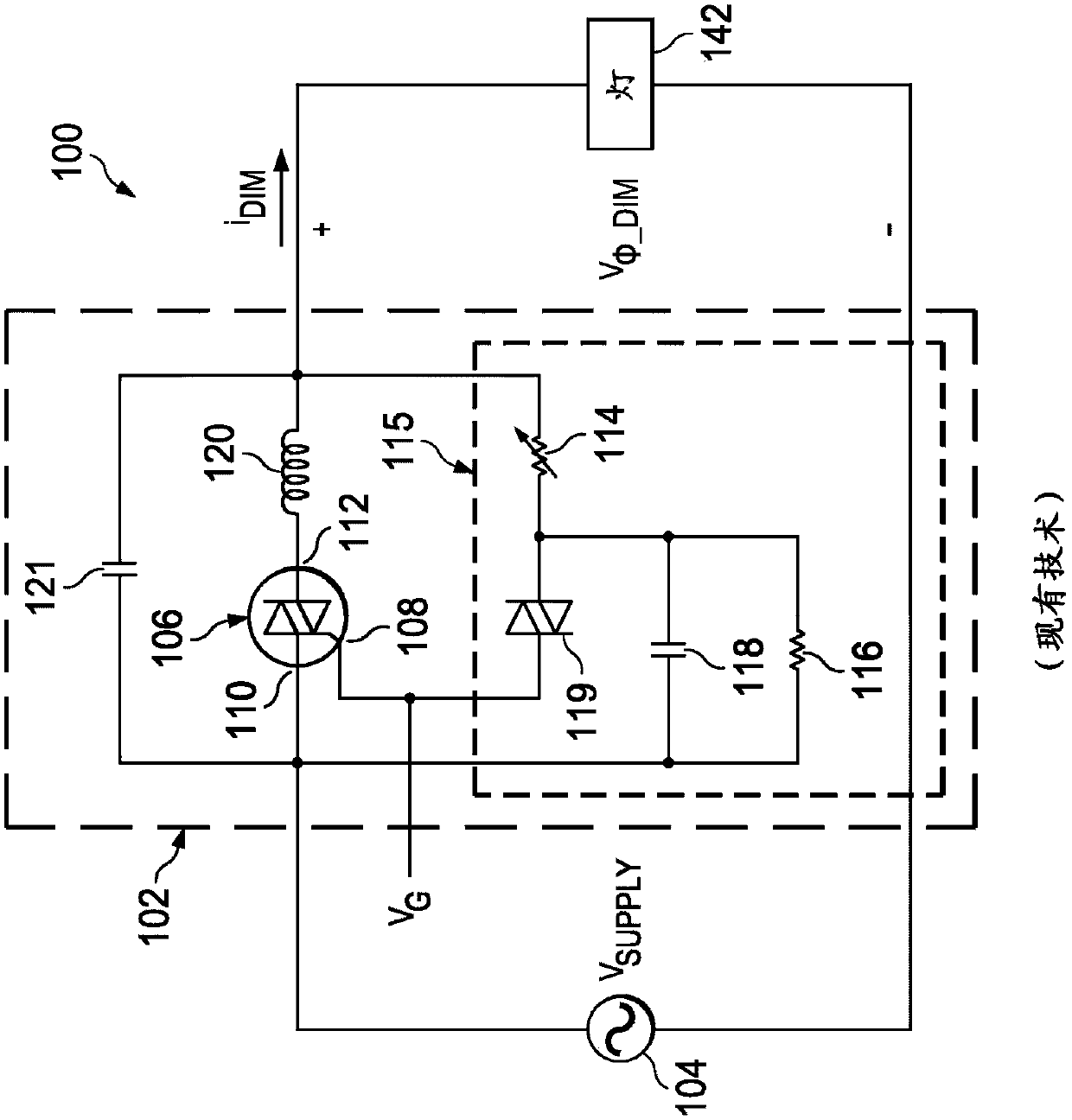
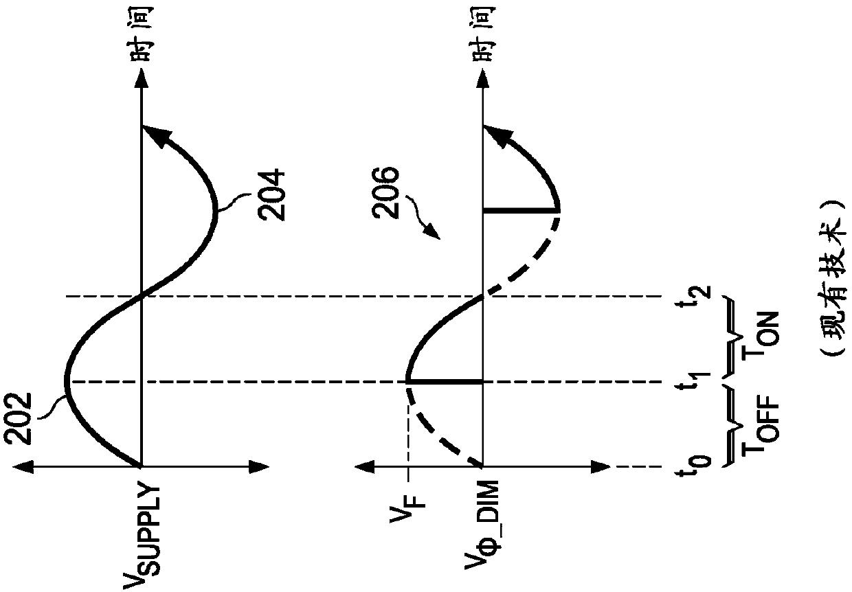
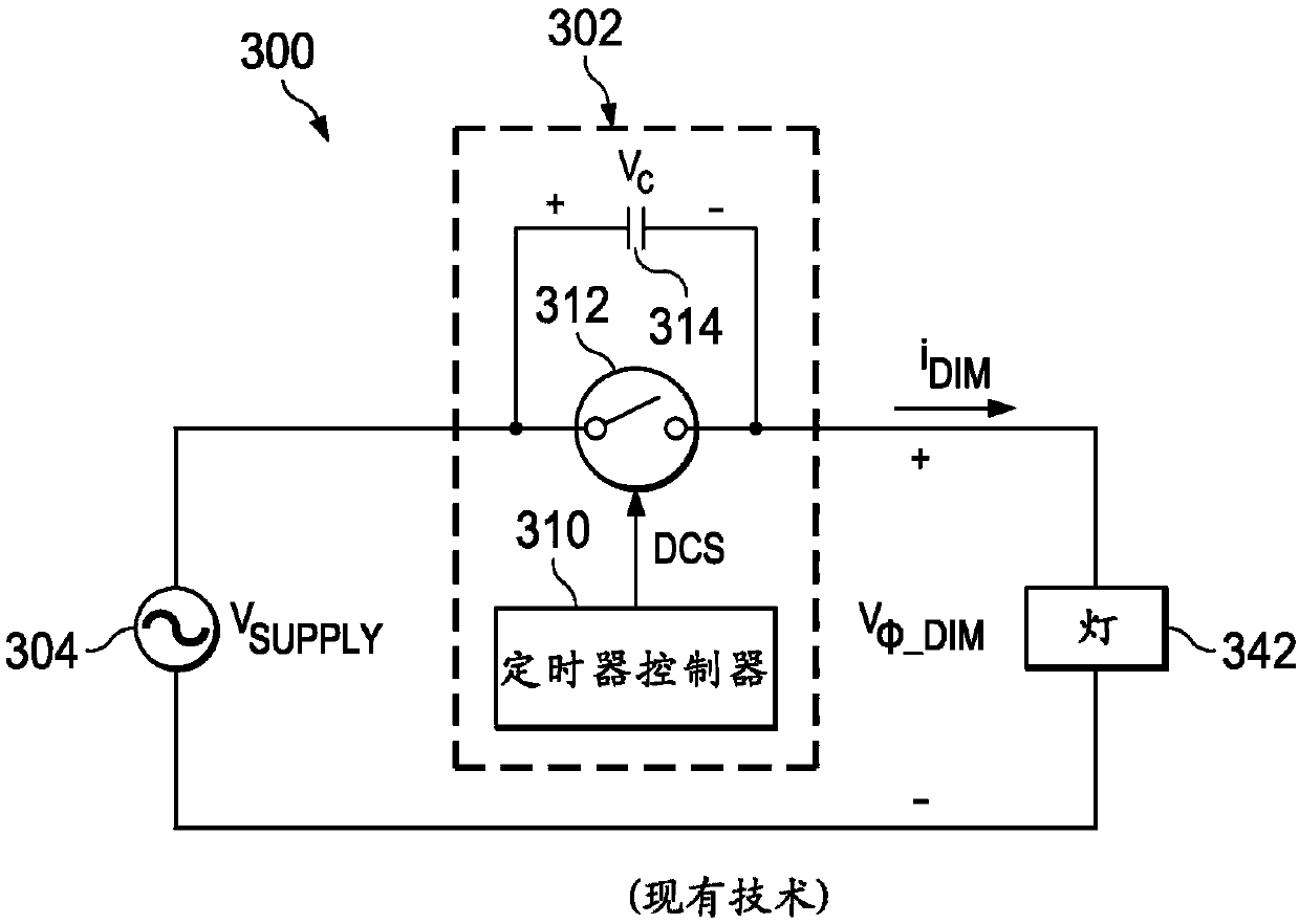
[0033] The dimmer 502 may include a dimmer for generating a dimming signal V to other elements of the lighting system 500 Φ_DIM Any system, device, or device in which the dimming signal V Φ_DIM Indicates the dimming level that causes the lighting system 500 to adjust the power delivered to the lamps and thus increase or decrease the brightness of the lamps 542 according to the dimming leve...


PUM


Abstract

According to embodiments of the present disclosure, methods and apparatus may include receiving an input waveform from a dimmer, wherein the input waveform is periodic at a first frequency. The methods and apparatus may also include generating an output waveform independent of a load coupled to the output waveform, wherein the output waveform is periodic at a second frequency substantially greater than the first frequency, wherein the second frequency of the output waveform and At least one of the amplitudes is based on a tangent angle of the input waveform indicative of a control setting for the dimmer.

Description

technical field [0001] The present disclosure relates generally to the field of electronics, and in particular, to low power lighting systems and methods related thereto, as compared to methods for ensuring compatibility between one or more low power lamps and the electrical infrastructure to which they are coupled. conventional method, which can provide a lower cost solution. Background technique [0002] Many electronic systems include circuitry such as switching power converters or transformers that interface with dimmers. The interface circuit delivers power to the load according to the dimming level set by the dimmer. For example, in a lighting system, a dimmer provides an input signal to the lighting system. The input signal represents a dimming level that causes the lighting system to adjust the power delivered to the lamps and thereby increase or decrease the brightness of the lamps according to the dimming level. There are many different types of dimmers. Genera...

Claims


Application Information

Patent Timeline
Patent Type & Authority Patents(China)
IPC IPC(8): H05B39/04H05B33/08H05B37/02H05B44/00
CPCH05B39/04H05B45/00H05B45/37H05B47/10H05B45/31H05B45/30H05B45/315H05B45/10
Inventor J·L·梅兰森E·J·金
Owner SIGNIFY HLDG BV
Why Eureka
Try Eureka