A device for punching holes for guide gear tubes of street lamp poles

A technology of punching device and gear tube, which is applied in the direction of positioning device, feeding device, storage device, etc., can solve the problems of inconvenient street lamp pole drilling, inconvenient street lamp pole guiding gear tube drilling, etc. Achieve the effects of convenient placement, convenient and firm support, and convenient rotation and adjustment

Inactive Publication Date: 2017-12-19
GANSU RONGBAO IND GRP
View PDF7 Cites 0 Cited by
  • Summary
  • Abstract
  • Description
  • Claims
  • Application Information

AI Technical Summary

Problems solved by technology

The existing punching machine is inconvenient to punch holes on the street light pole, and it is also inconvenient to punch holes on the guide gear tube of the street light pole

Method used


Image

  • A device for punching holes for guide gear tubes of street lamp poles

Examples


Embodiment Construction

[0013] The specific implementation manners of the present invention will be further described below in conjunction with the drawings and examples. The following examples are only used to illustrate the technical solution of the present invention more clearly, but not to limit the protection scope of the present invention.

[0014] The technical scheme of concrete implementation of the present invention is:

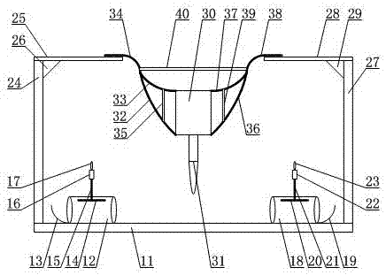
[0015] Such as figure 1 As shown, a device for punching holes for guide gear tubes of street lamp poles includes a bottom plate 11, a first guide cylinder 12 is arranged on one side of the bottom plate 11, the first guide cylinder 12 is arranged horizontally, and the inside of the first guide cylinder 12 The top is provided with a first lock piece 14, the first lock piece 14 is in the shape of an arc surface, the top of the first guide cylinder 12 is inserted with a first lock rod 15, and the first lock rod 15 is threadedly connected with the first guide cylinder 12, The...


PUM


Abstract

The invention discloses a punching device for a guide gear tube of a streetlamp lamp-post. The punching device comprises a bottom plate, wherein a guide barrel is arranged on the bottom plate; a locking plate is arranged on the inner top of the guide barrel; the top of the guide barrel is spliced with a locking rod; the locking rod is connected with the guide barrel through threads; the upper end of the locking rod is a free end; the lower end of the locking rod is connected with the locking plate; a side plate is arranged on the bottom plate; the end part of the side plate is provided with a limiting plate; a reinforcing base is arranged between the limiting plate and the side plate; a punch is arranged above the bottom plate; the lower part of the punch is provided with a punching shaft; one side of the punch is provided with a holding frame; and the holding frame is arranged on the limiting plate. The punching device is used for conveniently punching the clamped streetlamp lamp-post, and is convenient for forming a gear hole.

Description

technical field [0001] The invention relates to a hole punching device, in particular to a hole punching device for a guide gear tube of a street light pole. Background technique [0002] The punching machine is composed of four parts that cooperate with each other to complete the punching process. First, move the material to the scanning area of ​​the camera of the automatic punching machine. After the camera scans the image, it will process it and send a signal to the control part. After the control part receives the signal, it will further process and control the action of the transmission part, so that the punch is X on the plane. Axis, Y axis move, the pneumatic part starts to work after the movement is completed, and the solenoid valve controls the cylinder to perform the punching action. The automatic punching machine punches the printing positioning holes, and the whole action is done in one go, fast, accurate and efficient. The existing punching machine is inconve...

Claims


Application Information

Patent Timeline
Patent Type & Authority Patents(China)
IPC IPC(8): B21D28/32
CPCB21D28/28B21D28/32B21D43/003
Inventor 张宝
Owner GANSU RONGBAO IND GRP
Why Eureka
Try Eureka