Sieving feeding device

A feeding device and screening technology, applied in the field of plastic production, can solve the problems of unfavorable plastic particles, increased processing steps, and reduced efficiency, and achieve the effects of convenient collection, full screening, and improved efficiency.

Inactive Publication Date: 2016-09-21
重庆敏驰塑胶有限公司
View PDF0 Cites 1 Cited by
  • Summary
  • Abstract
  • Description
  • Claims
  • Application Information

AI Technical Summary

Problems solved by technology

[0003] Due to equipment limitations, the existing production process adopts the method of screening and separating the materials first, and then sending the materials to the next process, which increases the processing steps and reduces the efficiency.
[0004] In addition, most of the existing screening devices pass through the vibrating screen to make the plastic particles pass through t

Method used


Image

  • Sieving feeding device

Examples


Embodiment Construction

[0017] The present invention will be described in further detail below by means of specific embodiments:

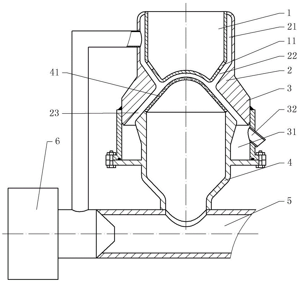
[0018] The reference signs in the drawings of the description include: hopper 1, discharge joint 2, connecting pipe 3, material selection pipe 4, feeding pipe 5, feeding fan 6, discharge hole 11, air duct 21, discharge loop 22, Annular feed port 23, waste bin 31, waste outlet 32, conical screen 41,.

[0019] The embodiment is basically as figure 1 Shown:

[0020] The screening and feeding device of this embodiment includes a hopper 1, a discharge joint 2, a material selection pipe 4, a feed pipe 5 and a feed fan 6; the discharge joint 2 is socketed on the outer periphery of the hopper 1, and the upper end of the discharge joint 2 is welded on On the side wall of the hopper 1; the lower end of the hopper 1 is in the shape of an inverted cone, and the upper side wall of the inverted tapered side wall is provided with a discharge hole 11; a gap with equal spacing is formed...


PUM


Abstract

The present patent discloses a sieving feeding device and relates to the field of plastic production. The sieving feeding device comprises a hopper, a discharge connector, a sorting pipe, a feeding pipe, and a feeding fan. The discharge connector sleeves the hopper, and an upper end of the discharge connector is fixedly connected to the hopper. A lower end of the hopper is inverted cone-shaped, and a discharge hole is formed in a sidewall of the lower end of the hopper. An equally spaced gap is formed between the hopper and the discharge connector. A cone-shaped sieve is fixed to an upper end of the sorting pipe, and the upper end of the sorting pipe is inserted into the discharge connector with an annular orifice formed between the sorting pipe and the discharge connector. A connecting sleeve is fixed to a lower end of the discharge connector, and further fixed to the sorting pipe with a waste material bin formed between the connecting sleeve and the sorting pipe. The feeding pipe communicates with the sorting pipe, and has one end connected to the feeding fan and the other end serving as a discharge orifice. The feeding fan further communicates with an air duct. The sieving feeding device is capable of sieving and cooling materials during feeding, thus allowing an improvement in production efficiency.

Description

technical field [0001] The invention relates to the field of plastic production, in particular to a screening and feeding device. Background technique [0002] At present, in the process of processing modified plastics, the modified plastics are often prepared into granular structures through extrusion equipment and extrusion dies. In order to ensure that the prepared plastic particles have uniform diameters and improve product quality Quality, the prepared plastic particles need to be screened and classified. [0003] Due to equipment limitations, the existing production process adopts the method of screening and separating the materials first, and then sending the materials to the next process, which increases the processing steps and reduces the efficiency. [0004] In addition, most of the existing screening devices pass through the vibrating screen to make the plastic particles pass through the screen. However, due to the high temperature of the freshly prepared plasti...

Claims


Application Information

Patent Timeline
IPC IPC(8): B29B13/10
CPCB29B13/10
Inventor 杨治焱
Owner 重庆敏驰塑胶有限公司
Why Eureka
Try Eureka