Spherical robot and control method

A spherical robot and spherical technology, applied in the field of robotics, can solve the problems of limited image clarity, low camera viewing angle, and high cost of spherical robots.

Active Publication Date: 2016-09-21
BOE TECH GRP CO LTD
View PDF6 Cites 30 Cited by
  • Summary
  • Abstract
  • Description
  • Claims
  • Application Information

AI Technical Summary

Problems solved by technology

[0003] Therefore, the above-mentioned spherical robot equipped with image recording equipment can be used in fields such as terrain detection, alien planet exploration, and radiation-corroded environment exploration. The application range is wide and the market prospect is huge. Inside the shell, the camera will not affect the movement of the spherical robot, and the spherical shell is designed to be transparent, so that the camera can observe the external situation and meet the function of image recording. The mechanical structure design of the robot is relatively complicated, and the viewing angle of the camera is low, which is easy to be blocked. In addition, the transparency of the outer material of the spherical shell limits the image clarity, and the high requirements for the outer material of the spherical shell lead to a spherical robot. The cost is relatively expensive, which is not conducive to marketing

Method used


Image

  • Spherical robot and control method
  • Spherical robot and control method
  • Spherical robot and control method

Examples


Embodiment Construction

[0051] The following will clearly and completely describe the technical solutions in the embodiments of the present invention with reference to the accompanying drawings in the embodiments of the present invention. Obviously, the described embodiments are only some, not all, embodiments of the present invention. Based on the embodiments of the present invention, all other embodiments obtained by persons of ordinary skill in the art without making creative efforts belong to the protection scope of the present invention.

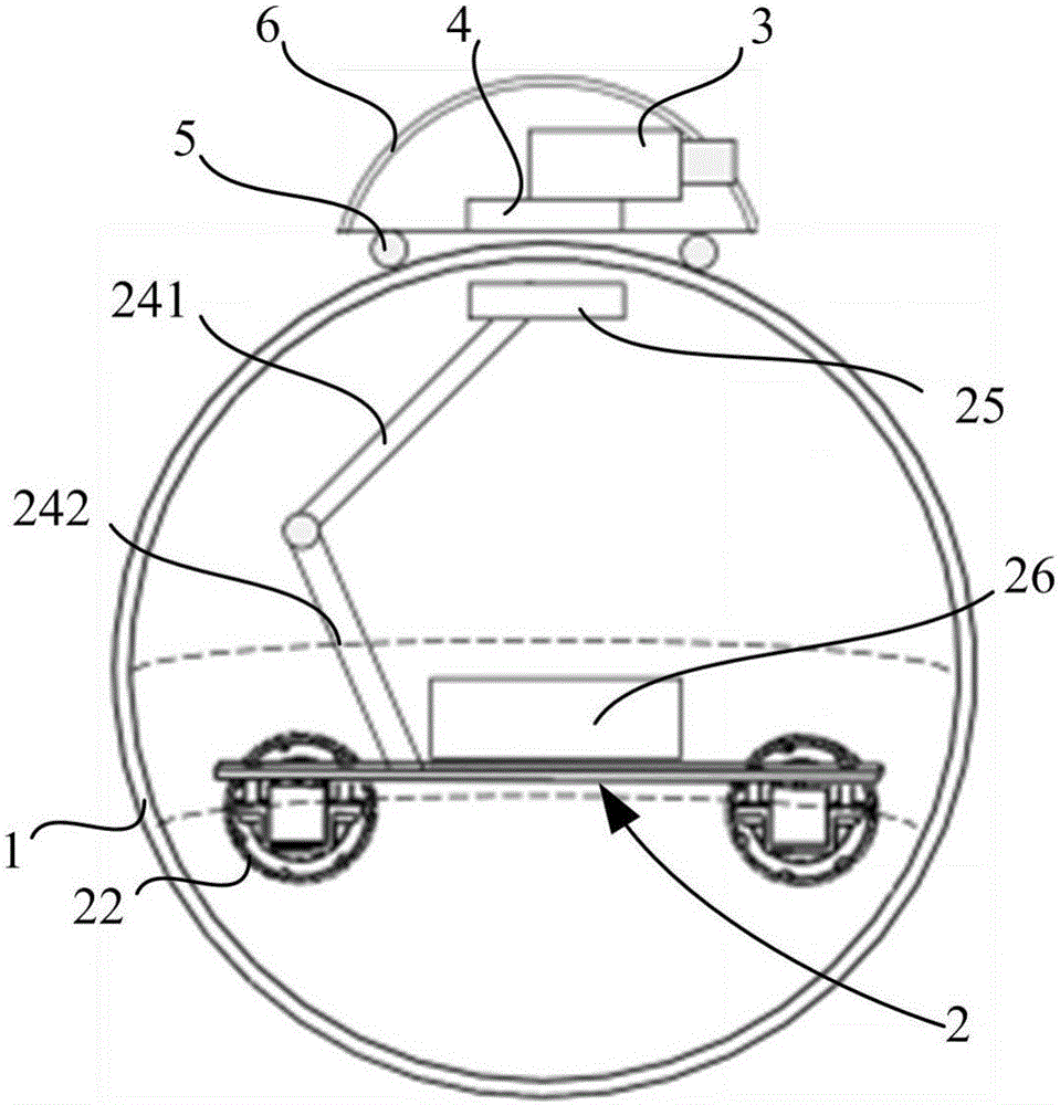
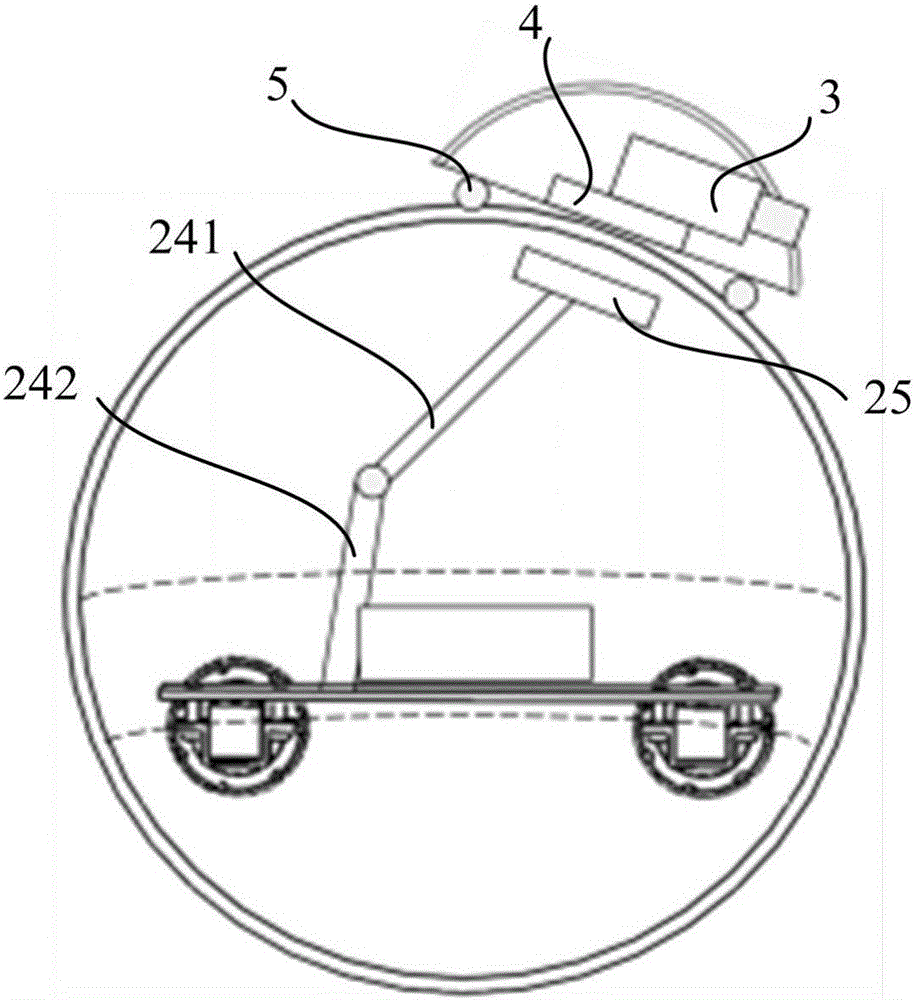
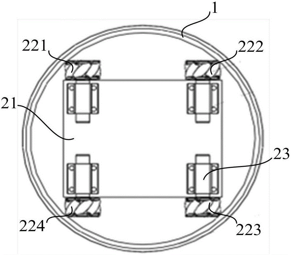
[0052] A kind of spherical robot provided by the embodiment of the present invention, such as figure 1 as well as figure 2 As shown, it includes a spherical housing 1, a spherical housing driving mechanism 2, and a camera assembly 3. The spherical housing driving mechanism 2 is installed in the spherical housing 1 to drive the spherical housing 1 to rotate around its center of sphere, and also includes a head shell body 6, the camera assembly 3 is installed ...


PUM


Abstract

The invention relates to the technical field of robots and discloses a spherical robot and a control method. The spherical robot comprises a spherical shell body, a spherical shell body driving mechanism and a camera assembly. The spherical shell body driving mechanism is installed in the spherical shell body so as to drive the spherical shell body to rotate around the sphere center of the spherical shell body. The spherical robot further comprises a head shell body, the camera assembly is installed in the head shell body, and the head shell body is located on the outer side of the spherical shell body, capable of sliding along the outer surface of the spherical shell body and provided with a first magnetic component. The spherical shell body driving mechanism is provided with a second magnetic component, and the first magnetic component is in magnetic connection with the second magnetic component. Moreover, the gravity center of a module formed by the spherical shell body driving mechanism, the head shell body and the camera assembly is lower than the sphere center of the spherical shell body in the vertical direction. The cameral assembly of the spherical robot is arranged outside the spherical shell body, capable of moving along with the spherical shell body and rotating relative to the spherical shell body, simple in structure, flexible and reliable in movement and good in image recording effect.

Description

technical field [0001] The invention relates to the technical field of robots, in particular to a spherical robot and a control method. Background technique [0002] A spherical robot refers to a robot that installs the drive system, sensors, and controllers inside a spherical shell, and drives the rolling motion of the spherical shell through the internal drive method to achieve omnidirectional motions such as forward, backward, and steering. Compared with wheeled or orbital and humanoid robots, it has a good dynamic and static balance, which makes the spherical robot not easy to be unstable due to collision, and can obtain the maximum after the instability. Stability, while the spherical robot has good terrain adaptability and good sealing characteristics, which can make it drive in sandy, humid and corrosive harsh environments. [0003] Therefore, the above-mentioned spherical robot equipped with image recording equipment can be used in fields such as terrain detection, ...

Claims


Application Information

Patent Timeline
Patent Type & Authority Applications(China)
IPC IPC(8): B62D57/02B64G1/16
CPCB62D57/02B64G1/16B62D57/00B60B19/003B60B19/14B60Y2200/40H04N23/51H04N23/65H04N23/695B64G1/1071B60R11/04B60R2011/004B60R2011/0092B62D11/02
Inventor 张忆非张莹赵凯丁洪利谷玉
Owner BOE TECH GRP CO LTD
Why Eureka
Try Eureka