Carrier taking and placing mechanism

A carrier and cylinder technology, which is applied in the field of carrier pick-and-place equipment, can solve the problems of easy falling off, machining shape size error, etc., and achieve the effect of improving the repeatability of positioning accuracy.

Active Publication Date: 2016-09-21
SUZHOU SECOTE PRECISION ELECTRONICS CO LTD
View PDF3 Cites 0 Cited by
  • Summary
  • Abstract
  • Description
  • Claims
  • Application Information

AI Technical Summary

Problems solved by technology

[0002] The pick-and-place of the carrier is widely used in the machinery industry. The methods usually used in the prior art are the claw cylinder method or the vacuum suction cup method. If the actual processing shape of the tool is inc

Method used


Image

  • Carrier taking and placing mechanism
  • Carrier taking and placing mechanism
  • Carrier taking and placing mechanism

Examples


Example Embodiment

[0021] The technical solutions of the present invention will be further described below in conjunction with the drawings and specific implementations.

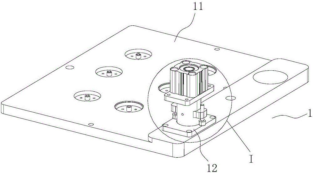
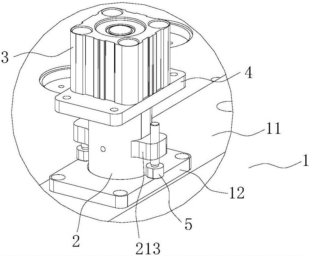
[0022] This embodiment provides a carrier pick-and-place mechanism, such as Figure 1 to 5 As shown, the carrier pick-and-place mechanism includes a carrier 1, an adjusting assembly 2, an air cylinder 3, a fixed plate 4, a ball 6, a moving shaft 8 and a driving assembly (not shown in the figure), wherein,

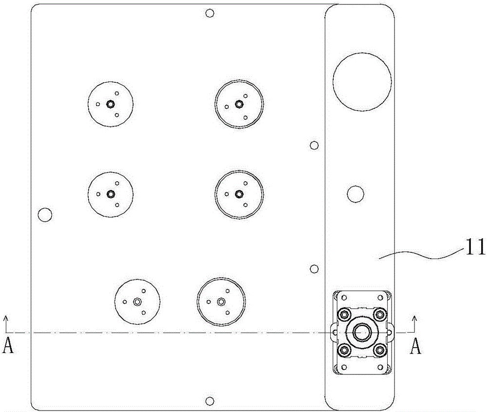
[0023] The carrier 1 includes a carrier body 11 on which a fixed block 12 is fixedly arranged therethrough, and the carrier body 11 and the fixed block 12 are connected by screws; the fixed block 12 is provided with A perforating hole, one end of the perforating hole is set as a tapered hole 121, the diameter of the tapered hole 121 gradually increasing along the extending direction of the piston rod 31 of the cylinder 3.

[0024] The adjusting component 2 is slidably penetrated through the carrier 1. Specifically, refer to Fig...


PUM


Abstract

The invention relates to related technical fields of carrier taking and placing equipment, and in particular, discloses a carrier taking and placing mechanism. A cylinder drives a moving shaft to downwards move, and a ball is butted against the inner wall of a conical hole through a slope structure, so that the fixation of an adjusting module corresponding to a carrier is realized, the repeated positioning precision in clamping of the carrier is improved, the clamping of the carrier is not influenced by machining errors of a through hole, and the condition of falling of the carrier caused by larger weight of the carrier in taking and placing of the carrier is prevented; and when the carrier needs to be shifted away, the cylinder drives the moving shaft to upwards move so as to deviate the slope structure from the ball, a driving module drives a fixed plate to upwards moves, the fixed plate drives the adjusting module to upwards move, and the inner wall of the conical hole is ejected against the ball into a clamping groove and an accommodating cavity so as to realize deviation of the carrier taking and placing mechanism from the carrier.

Description

technical field [0001] The present invention relates to the technical field of carrier pick-and-place equipment, in particular to a carrier pick-and-place mechanism. Background technique [0002] The pick-and-place of the carrier is widely used in the machinery industry. The methods usually used in the prior art are the claw cylinder method or the vacuum suction cup method. Slight errors will occur if the actual processing shape of the tool is inconsistent. When using the vacuum suction cup, if the weight of the carrier is large, it is easy to fall off when the moving speed is fast, and it is only applicable to the case of a small weight of the carrier. Contents of the invention [0003] The purpose of the present invention is to provide a carrier pick-and-place mechanism to improve the repeated positioning accuracy when picking up the carrier and avoid the carrier falling off when the weight of the carrier is heavy. [0004] For reaching this purpose, the present inventi...

Claims


Application Information

Patent Timeline
IPC IPC(8): B65G47/88B65G47/90
CPCB65G47/88B65G47/90
Inventor 孙丰
Owner SUZHOU SECOTE PRECISION ELECTRONICS CO LTD
Why Eureka
Try Eureka