A combined vertical cable pay-off frame

A pay-off frame and cable technology, which is applied in the field of wire release, can solve the problems of support wheel and chassis wear, affect the construction progress, support wheel burden, etc., and achieve the effect of convenient disassembly and installation, improvement of construction safety, and beautiful style

Active Publication Date: 2019-06-18
STATE GRID CORP OF CHINA +1
View PDF1 Cites 0 Cited by
  • Summary
  • Abstract
  • Description
  • Claims
  • Application Information

AI Technical Summary

Problems solved by technology

However, ordinary cable reels weigh several hundred kilograms, and some weigh several tons. Such heavy cable reels lie on the deployment device and are only driven by friction, which will inevitably cause damage to the supporting wheels on the chassis. Heavy burden, long-term use will inevitably cause serious wear and tear on the support wheels and the chassis, and a lot of electronic equipment is used on it, and it is also prone to failure in an environment with poor construction conditions, which will affect the construction progress

Method used


Image

  • A combined vertical cable pay-off frame
  • A combined vertical cable pay-off frame
  • A combined vertical cable pay-off frame

Examples


Embodiment Construction

[0024] Below in conjunction with accompanying drawing description and specific embodiment, the present invention will be described in further detail:

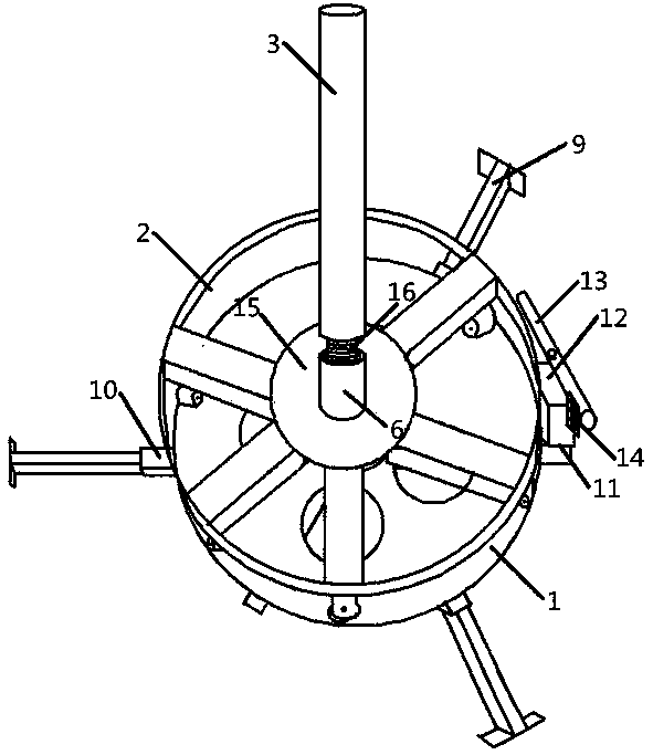
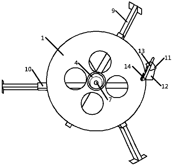
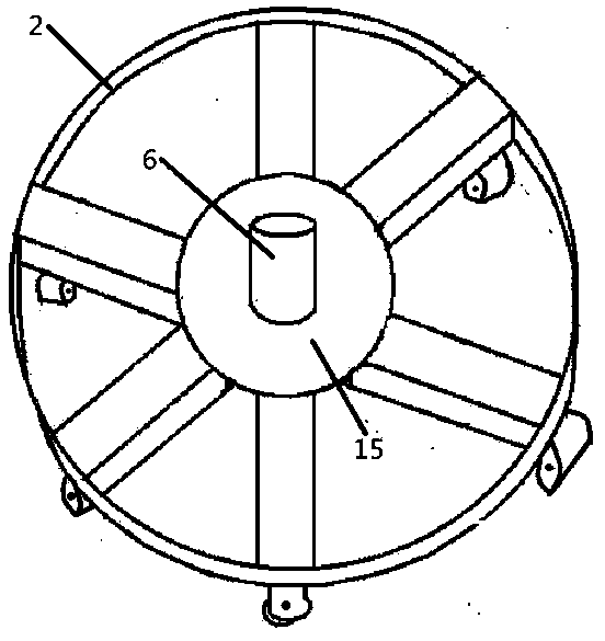
[0025] A combined vertical cable pay-off frame, comprising a base 1 made of cast steel, a runner 2 and a vertical shaft 3, the center of the base 1 is provided with a circular groove 4, and the bottom of the base 1 is provided with three telescopic Fixed rod 9, described telescopic fixed rod 9 is installed in the square tube 10, and described square tube 10 is fixed on the bottom of base 1, and the junction of three square tubes 10 is the center of base 1, and the adjacent square tube 10 The center of the bottom of the runner 2 is provided with a tapered bearing 5, the diameter of the outer ring of the tapered bearing 5 is equal to the diameter of the circular groove 4, and the height of the tapered bearing 5 is the same as that of the circular groove 4. The depth of the shaped groove 4 is equal, the outer edge of the bottom of...


PUM


Abstract

The invention relates to a combined vertical cable pay-off rack comprising a base, a runner and a vertical shaft. The combined vertical cable pay-off rack is characterized in that a circular groove is formed in the center of the base; a conical bearing is arranged in the center of the bottom of the runner; the diameter of an outer ring of the conical bearing is equal to that of the circular groove; the height of the conical bearing is equal to the depth of the circular groove; rollers are uniformly distributed along the circumference of the outer edge of the bottom of the runner; a vertical cylinder is arranged in the center of the upper part of the runner; and the vertical shaft is rotatably connected together with the vertical cylinder. The combined vertical cable pay-off rack is simple in structure, convenient to mount and transport as well as take up and pay off, good in stability and very long in service life.

Description

technical field [0001] The invention relates to a set-up wire, in particular to a combined vertical cable pay-off frame. Background technique [0002] At present, the domestic laying of high-voltage cables basically uses a tractor to pull the cable out of the cable reel. After the cable reaches the conveyor, the conveyor provides the conveying force, and the tractor also provides part of the traction force at this time, and then pulls the cable to drive the cable reel to rotate. purpose of expansion. The cable reel is only supported by the cross bar between the elevators. When the tractor and conveyor pull the cable to drive the cable reel, the cable reel and the cross bar will have rolling friction. Even if it is rolling friction, due to the total The weight is generally large, and the rolling friction between the cable reel and the cross bar will be relatively large, so the tension on the cable is relatively large, which will easily cause damage to the cable and cause los...

Claims


Application Information

Patent Timeline
Patent Type & Authority Patents(China)
IPC IPC(8): B65H49/28B65H59/04
CPCB65H49/28B65H59/043B65H2408/241B65H2701/34
Inventor 秦子琪秦加军周强
Owner STATE GRID CORP OF CHINA
Why Eureka
Try Eureka