
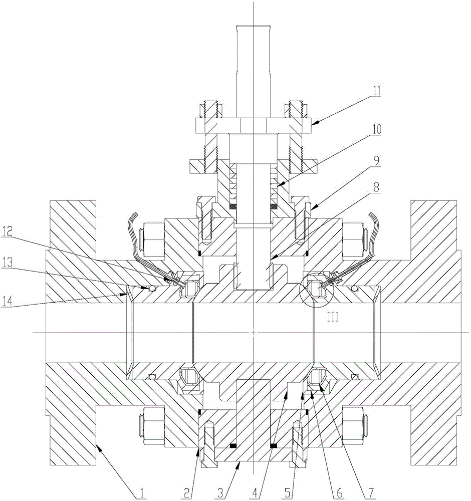
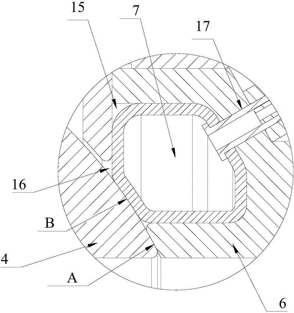
High-pressure ball valve sealed by inflatable type flexible sealing rings arranged inside valve seats

A flexible sealing and inflatable technology, applied in valve devices, cocks including cut-off devices, engine components, etc., can solve the problems of easy wear of ball valves, excessive leakage, valve leakage, etc., and achieve the effect of ensuring the sealing effect.

Inactive Publication Date: 2016-09-21
YUEYANG DONGFANG AUTOMATIC CONTROL ENG EQUIP
View PDF7 Cites 9 Cited by
  • Summary
  • Abstract
  • Description
  • Claims
  • Application Information

AI Technical Summary

Problems solved by technology

[0008] Usually, during the opening and closing process of the valve, the ball rotates, and the sealing surface of the valve seat and the spherical surface that are always close together are worn under the action of spring force and medium pressure; after a long or short period of time, when the wear After reaching a certain level, the valve will leak, and eventually the valve will fail due to excessive leakage
[0009] However, it is obvious that the sealing surfaces of the valve seat and the sphere of the above-mentioned 3 main types of sealing structures will be worn due to the rotation of the valve sphere, so the traditional ball valves installed with the above-mentioned 3 types of sealing structures are prone to wear and leakage. defect

Method used


Image

  • High-pressure ball valve sealed by inflatable type flexible sealing rings arranged inside valve seats
  • High-pressure ball valve sealed by inflatable type flexible sealing rings arranged inside valve seats

Examples


Embodiment Construction

[0058] The technical solutions of the present invention will be clearly and completely described below in conjunction with the accompanying drawings. Apparently, the described embodiments are some of the embodiments of the present invention, but not all of them. Based on the embodiments of the present invention, all other embodiments obtained by persons of ordinary skill in the art without making creative efforts belong to the protection scope of the present invention.

[0059]In the description of the present invention, it should be noted that the terms "center", "upper", "lower", "left", "right", "vertical", "horizontal", "inner", "outer" etc. The indicated orientation or positional relationship is based on the orientation or positional relationship shown in the drawings, and is only for the convenience of describing the present invention and simplifying the description, rather than indicating or implying that the referred device or element must have a specific orientation, o...


PUM


Abstract

The invention discloses a high-pressure ball valve sealed by inflatable type flexible sealing rings arranged inside valve seats. The high-pressure ball valve comprises valve covers, a valve body, a supporting shaft, a ball body, end covers, the valve seats, the inflatable type flexible sealing rings, a valve rod, a stuffing box, fillers and a gland; an inner ring sealing sphere of each valve seat clings to the surface of the ball body to form a first sealing structure; each inflatable type flexible sealing ring inflated at an annular opening clings to the surface of the ball body to form a second sealing structure. According to the high-pressure ball valve sealed by inflatable type flexible sealing rings arranged inside valve seats, by controlling the inflation of the inflatable type flexible sealing rings, construction and elimination of the second sealing structure can be realized; abrasion of a sealing surface between the valve seats and the ball body, caused by rotation of the ball body, can be greatly reduced; meanwhile, the sealing surface of each valve seat is ensured to always cling to the sphere completely to guarantee the sealing effect.

Description

technical field [0001] The invention relates to the technical field of ball valves, in particular to a high-pressure inflatable flexible sealing ring-sealed ball valve with a built-in valve seat. Background technique [0002] As we all know, at home and abroad, the fixed ball valve generally adopts the sealing structure of the floating valve seat, that is, the ball (valve core) is fixed, the valve seat is floating, and the valve seat relies on the elastic force generated by the spring placed on the end face and the pressure of the medium. The seat is pushed tightly against the ball to establish the specific pressure of the seal. [0003] Generally speaking, valve designers hope to reduce or completely eliminate the gap between the sealing surface of the valve seat and the outer surface of the ball as much as possible, so as to reduce the leakage risk of the valve. [0004] At present, there are mainly three structural types of the sealing structure between the valve seat an...

Claims


Application Information

Patent Timeline
Patent Type & Authority Applications(China)
IPC IPC(8): F16K5/06F16K5/20
CPCF16K5/06F16K5/205
Inventor 吴军
Owner YUEYANG DONGFANG AUTOMATIC CONTROL ENG EQUIP
Learn More