High-cooling intelligent LED lamp

An LED lamp, high heat dissipation technology, applied in lighting and heating equipment, cooling/heating device of lighting device, lighting device, etc., can solve the problems of poor signal reception performance, unreasonable design, affecting user experience, etc. Intelligent high effect

Inactive Publication Date: 2016-09-21
彭曙光
1 Cites 6 Cited by

AI-Extracted Technical Summary

Problems solved by technology

[0002] At present, such as a kind of LED smart lamp disclosed in the patent of publication number: CN204254342U, more and more lamps are realized by intelligent control, smart home has become the mainstream of current lamps, and the current struc...

Method used

A kind of high heat dissipation intelligent LED lamp described in the present embodiment also includes the video monitor 5 that is used for real-time monitoring, and described video monitor 5 is connected with main control chip signal, and described video monitor 5 is located at The outer wall of the housing 1; the video monitor 5 can monitor in real time, improving the intelligence and practicability of the LED lamp.
A kind of high heat dissipation intelligent LED lamp described in the present embodiment, an isolation groove G4 is arranged in the middle of the first microstrip unit and the second microstrip unit, and semiconductor is filled in the isolation groove G4, and the The semiconductor is silicon dioxide. It can effectively reduce mutual coupling, enhance isolation and reduce standing wave ratio.
[0036] The intelligent circuit also includes a WIFI module and a communication antenna, and the WIFI module is respectively connected to the main control chip and the communication antenna signal; the communication antenna is located in the communication cavity 8. Generally, it...

Abstract

The invention discloses a high heat dissipation intelligent LED lamp, which comprises a shell and a metal plate arranged in the shell, the top surface of the metal plate is provided with a ventilation column through the middle, the metal plate is provided with a first opening, the first The opening communicates with the opening at one end of the ventilation column, and a lamp panel is provided on the bottom of the metal plate, and the lamp panel includes a concentric ring-shaped first LED light-emitting group, a second LED light-emitting group and a third LED light-emitting group; through Reasonable setting realizes the effect of self-radiation, and also has the function of adjusting multiple light types, which is highly intelligent and durable.

Application Domain

Technology Topic

Image

  • High-cooling intelligent LED lamp
  • High-cooling intelligent LED lamp
  • High-cooling intelligent LED lamp

Examples

  • Experimental program(1)

Example Embodiment

[0034] The present invention will be described in further detail below with reference to the accompanying drawings and specific embodiments, but the scope of implementation of the present invention is not limited thereto.
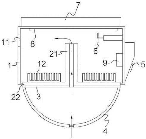
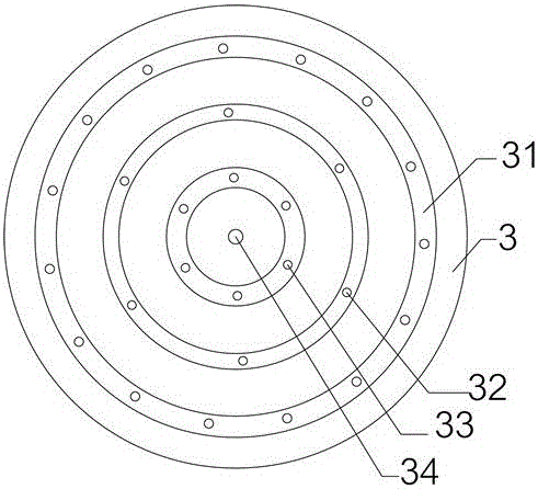
[0035] like Figure 1 to Figure 9 As shown, a high heat dissipation smart LED lamp described in this embodiment includes a casing 1 and a metal plate 22 arranged in the casing 1. The top surface of the metal plate 22 is provided with a central ventilation column 21, The metal plate 22 is provided with a first opening 34, and the first opening 34 communicates with the opening at one end of the ventilation column 21; when in use, due to the air pressure difference between the top end and the low end of the ventilation column 21, the ventilation column 21 will have air pressure difference. An updraft is formed, which takes away heat and forms a way of self-dissipation. The bottom surface of the metal plate 22 is provided with a lamp plate 3, and the lamp plate 3 includes a first LED light-emitting group 31, a second LED light-emitting group 32 and a third LED light-emitting group 33 that are concentrically arranged and are annular; A circuit box 9 is arranged on the inner wall of the housing 1, and the circuit box 9 is provided with an intelligent circuit; the outer top surface of the housing 1 is provided with a battery cavity 7 equipped with a battery, and the battery is used to supply power to the intelligent circuit; The inner top surface of the housing 1 is provided with a communication cavity 8; the intelligent circuit includes a main control chip, and a first driver chip, a second driver chip, and a third driver chip that are electrically connected to the main control chip, respectively; The first driving chip, the second driving chip and the third driving chip are respectively electrically connected with the first LED lighting group 31, the second LED lighting group 32 and the third LED lighting group 33; The LED light-emitting group 32 and the third LED light-emitting group 33 can be lights of the same color or lights of different colors, and can be lit at the same time or separately, which is convenient to control and highly intelligent.
[0036] The intelligent circuit further includes a WIFI module and a communication antenna, the WIFI module is signal-connected with the main control chip and the communication antenna respectively; the communication antenna is arranged in the communication cavity 8 . Generally, a mobile terminal is also included. The mobile terminal is used to control the smart light, and the mobile terminal can be a smart phone; the LED light achieves the effect of self-heating through reasonable settings, and also has the adjustment function of multiple light species, with high intelligence and high Built to last. In the smart LED lamp with high heat dissipation described in this embodiment, the colors of the first LED lighting group 31 , the second LED lighting group 32 and the third LED lighting group 33 are different. Different atmospheres can be adjusted.
[0037]In the smart LED lamp with high heat dissipation described in this embodiment, the communication antenna includes a rectangular PCB reflector G1, and a microstrip antenna is provided on the PCB reflector G1; the microstrip antenna includes a vertically symmetrical, The first microstrip unit and the second microstrip unit with the same shape; the first microstrip unit and the second microstrip unit both include a first microstrip line G61, from the first microstrip line G61 to the PCB reflector G1 The second microstrip line G62 extending from the center and the third microstrip line G63 extending from the second microstrip line G62 to the center of the PCB reflector G1; wherein, the first microstrip line G61 to the third microstrip line G63 are all are in the same direction, and the direction is the direction of the long side of the PCB reflector G1; one end of the first microstrip line G61, one end of the second microstrip line G62, and one end of the third microstrip line G63 are aligned. The other end of a microstrip line G61, the other end of the second microstrip line G62, and the other end of the third microstrip line G63 are stepped; the third microstrip line G63 extends toward the center of the PCB reflector G1 There are a plurality of arch bridge-shaped radiation ring arms G65; each radiation ring arm G65 is provided with a decoupling window G64 with an arc at one end and a rectangle at the other end; wherein, the direction of the decoupling window G64 is that the PCB reflector G1 is short. The side of the first microstrip line G61 away from the center of the PCB reflector G1 is provided with a plurality of rectangular recesses G66; it also includes a first feeding sheet G51 and a second feeding sheet G52 for power feeding, The first feeding sheet G51 and the second feeding sheet G52 are arranged on the same side of the PCB reflector G1, and the first feeding sheet G51 is electrically connected to the first microstrip line G61 of the first microstrip unit; The two feeding sheets G52 are electrically connected with the third microstrip line G63 of the second microstrip unit through a feeding thin strip;
[0038] Through no less than 550 times of microstrip circuit structure design, and no less than 500 times of simulation tests and parameter adjustment, the above-mentioned antenna structure is finally determined. The antenna has a wide frequency range and good isolation and directivity. and gain performance. like Figure 7 , the available frequency range of the antenna bandwidth is as high as 1.7GHz to 2.65GHz; it basically meets the requirements of the communication frequency band, and its gain is also high, and the average gain in the frequency band is greater than 8.952dBi; it meets the actual use needs.
[0039] In the smart LED lamp with high heat dissipation described in this embodiment, the number of decoupling windows G64 of each third microstrip line G63 is 9, and the length of the middle decoupling window G64 is the longest, and the decoupling windows G64 in the middle have the longest length. The lengths of the decoupling windows G64 from the decoupling windows G64 to the two sides are successively reduced. When this number is met, its data is as follows Figure 8. The available frequency range of the overall antenna system bandwidth has reached 1.6GHz to 2.85GHz; its gain has also increased significantly, and the average gain in the frequency band is greater than 9.4dBi, which is about 0.3dBi higher than that; in addition, its isolation degree, if the isolation degree within the frequency band, the isolation degree perform better, such as Figure 8 , it can be seen in S3 that the isolation is greater than 25.5dB in the frequency range. Its directionality is also good, such as Figure 9 As mentioned above, it is an omnidirectional antenna.
[0040] In the smart LED lamp with high heat dissipation described in this embodiment, the number of rectangular pits G66 of each first microstrip line G61 is 29-35. In the high heat dissipation smart LED lamp described in this embodiment, if the number of decoupling windows G64 of each third microstrip line G63 is N, and the width of the rectangular pit G66 is set to K, then the second microstrip line The length L of G62 is 9.5N*K. After setting the above parameter limits, it is found through a lot of experiments and simulations that the gain is more stable and the isolation is kept at a high level. The above parameters are obtained through continuous testing and adjustment, and are the most stable and best-performing specific parameters. The specific actual test results are calculated by the HFSS15 software, and the available frequency range of the overall system antenna bandwidth is 1.6GHz to 2.8GHz. Internal frequency modulation; The average gain in the frequency band is greater than 9.35dBi, and the impedance is reduced; the isolation degree in the frequency range is greater than 26dB; in the actual test, it is found that changes in the external environment, such as changes in temperature and magnetic field effects, are within a certain range, such as temperature around 10 degrees. Amplitude changes, when the above parameters and specific values ​​are used, the stability is very strong, and the frequency band retention is good.
[0041] In the smart LED lamp with high heat dissipation described in this embodiment, an isolation groove G4 is arranged between the first microstrip unit and the second microstrip unit, and the isolation groove G4 is filled with semiconductors, and the semiconductors are two Silicon oxide. It can effectively reduce mutual coupling, enhance isolation, and reduce standing wave ratio.
[0042] The high heat dissipation smart LED lamp described in this embodiment further includes a parasitic oscillator unit G2 disposed on the side of the PCB reflector G1 away from the first feeding sheet G51 and the second feeding sheet G52. The parasitic oscillator unit G2 includes a first rectangular arm and a second rectangular arm extending from the first rectangular arm to one side of the first microstrip unit. The parasitic oscillator unit G2 can effectively increase the bandwidth.
[0043] In the intelligent LED lamp with high heat dissipation described in this embodiment, an isolation microstrip ring G3 is further arranged on the periphery of the PCB reflector G1. Effectively improve isolation and reduce interference.
[0044] The high heat dissipation intelligent LED lamp described in this embodiment further includes a video monitor 5 for real-time monitoring, the video monitor 5 is signal-connected to the main control chip, and the video monitor 5 is arranged in the housing 1 The outer side wall of the LED lamp; the video monitor 5 can monitor in real time, and improve the intelligence and practicability of the LED lamp.
[0045] The smart LED lamp with high heat dissipation described in this embodiment further includes a fan module 6 disposed on the inner wall of the housing 1 and a temperature sensor disposed on the ventilation column 21 . The temperature sensor and the fan module 6 are connected to the main controller. Chip signal connection; a second opening 11 is provided on the inner wall of the housing 1 opposite to the inner wall of the fan module 6; when the temperature is too high, the main control chip controls the operation of the fan module 6, and the airflow at the top of the ventilation column 21 is adjusted. Speed ​​up and improve heat dissipation.
[0046] In the smart LED lamp with high heat dissipation described in this embodiment, the top surface of the metal plate 22 is further provided with heat dissipation fins 12, and the heat dissipation fins 12 are aluminum alloy heat dissipation fins 12, so as to improve the heat dissipation characteristics.
[0047] The smart LED light with high heat dissipation described in this embodiment further includes a Bluetooth module for Bluetooth communication, the Bluetooth module is signal-connected to the communication antenna and the main control chip; it can be used for ordinary Bluetooth mobile phones, and Use without WIFI. Used to bypass third-party networks and directly communicate with the target device in two directions.
[0048] The high heat dissipation intelligent LED lamp described in this embodiment further includes a lens lampshade 4 for uniform light, the lens lampshade 4 is arranged under the lamp plate 3 , and the bottom of the lens lampshade 4 is provided with a third opening. The third opening does not obstruct the airflow into the ventilation column 21 .
[0049] The above is only a preferred embodiment of the present invention, so all equivalent changes or modifications made according to the structure, features and principles described in the scope of the patent application of the present invention are included in the protection scope of the patent application of the present invention.

PUM

no PUM

Description & Claims & Application Information

We can also present the details of the Description, Claims and Application information to help users get a comprehensive understanding of the technical details of the patent, such as background art, summary of invention, brief description of drawings, description of embodiments, and other original content. On the other hand, users can also determine the specific scope of protection of the technology through the list of claims; as well as understand the changes in the life cycle of the technology with the presentation of the patent timeline. Login to view more.

Similar technology patents

Method for guiding to photograph and mobile terminal

ActiveCN103401994AResolve problems presented by the inability to articulate compositional ideas to othersImprove intelligenceTelevision system detailsDigital data processing detailsComputer engineeringMultimedia
Owner:GUANGDONG OPPO MOBILE TELECOMM CORP LTD

Classification and recommendation of technical efficacy words

Why Eureka
Try Eureka