
A FPGA-based system timing device and timing method

A time and internal clock technology, applied in the direction of generating/distributing signals, etc., can solve the same problem of card timing, and achieve the effect of high accuracy, high precision and high reliability

Active Publication Date: 2019-05-17
NANJING GUODIAN NANZI WEIMEIDE AUTOMATION CO LTD
View PDF6 Cites 0 Cited by
  • Summary
  • Abstract
  • Description
  • Claims
  • Application Information

AI Technical Summary

Problems solved by technology

Solve the problem of timing synchronization of each card

Method used


Image

  • A FPGA-based system timing device and timing method
  • A FPGA-based system timing device and timing method
  • A FPGA-based system timing device and timing method

Examples


Embodiment Construction

[0022] In order to make the object, technical solution and advantages of the present invention more clear, the present invention will be further described in detail below in conjunction with the examples. It should be understood that the specific embodiments described here are only used to explain the present invention, not to limit the present invention.

[0023] The application principle of the present invention will be described in detail below in conjunction with the accompanying drawings.

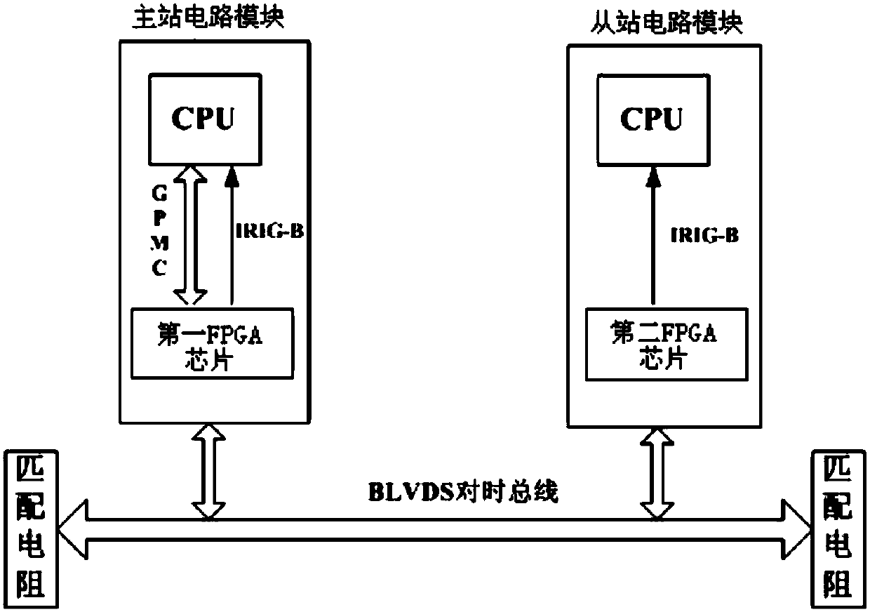
[0024] A system timing device based on FPGA, comprising a master station circuit module and a plurality of slave station circuit modules; the master station circuit module and a plurality of slave station circuit modules are electrically connected by a BLVDS bus; the master station circuit module includes sequentially Connected CPU chip, GPMC interface and the first FPGA chip, the first FPGA chip includes the time setting register, internal clock module, IRIG-B coding module and the fi...


PUM


Abstract

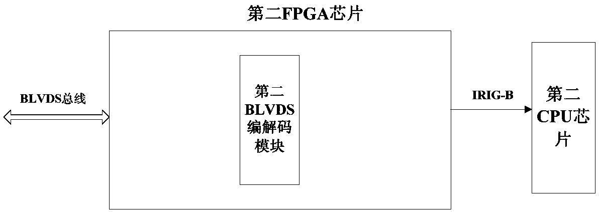
The invention discloses a system clock synchronization device based on a FPGA and a clock synchronization method. The system clock synchronization device comprises a master station circuit module and a plurality of slave station circuit modules. The master station circuit module and the plurality of slave station circuit modules are electrically connected through a BLVDS bus. The master station circuit module comprises a CPU chip, a GPMC interface, and a first FPGA chip connected in sequence. The first FPGA chip comprises a time setting register, an internal clock module, and an IRIG-B encoding module, and a first BLVDS coding and decoding module connected in sequence. The output end of the IRIG-B encoding module is also connected with the input end of a first CPU chip. Each of the plurality of slave station circuit modules comprises a second FPGA chip and a second CPU chip. The second FPGA chip comprises a second BLVDS coding and decoding module. The device uses the FPGA to compile the IRIG-B to send to the module according to the time sequence of the IRIG-B, and sends signals according to an IRIG-B coded format, and uses the BLVDS bus to send the code to each clock synchronization card piece, to solve problems clock synchronization of each card piece.

Description

technical field [0001] The invention belongs to the field of monitoring equipment, and in particular relates to an FPGA-based system time synchronization device and a time synchronization method. Background technique [0002] When there are multiple cards for recording events in one device, the real-time and synchronization issues of recording event time are often worthy of attention. In the prior art, network time synchronization or IRIG-B time synchronization is usually used, and the network time synchronization error delay is large, which cannot be applied to occasions with high time accuracy; IRIG-B (InterRange Instrumentation Group) time synchronization, referred to as B code time synchronization , which is widely used in the field of industrial control due to its high stability and reliability. However, IRIG-B time synchronization requires an external clock source. If the clock source cannot be accessed, the time synchronization of each card cannot be completed. There...

Claims


Application Information

Patent Timeline
Patent Type & Authority Patents(China)
IPC IPC(8): G06F1/12G06F1/14
CPCG06F1/12G06F1/14
Inventor 李伟黄作兵杨淑萍赵永黄蕾
Owner NANJING GUODIAN NANZI WEIMEIDE AUTOMATION CO LTD
Learn More