A motor rotor axial clearance adjustment machine

A technology of axial clearance and motor rotor, which is applied in the manufacture of motor generators, stator/rotor bodies, electrical components, etc., can solve the problems of inability to guarantee the stability of motor quality, time-consuming adjustment of axial clearance, etc., to achieve clearance The effect of accurate adjustment, improved efficiency and accurate detection

Active Publication Date: 2018-05-22
JIANGSU LANGXIN ELECTRIC
View PDF7 Cites 0 Cited by
  • Summary
  • Abstract
  • Description
  • Claims
  • Application Information

AI Technical Summary

Problems solved by technology

Adjusting the axial play with the aid of the separately supplied adjusting shims is time-consuming
And there is no way to guarantee the stability of the overall quality of the motor produced

Method used


Image

  • A motor rotor axial clearance adjustment machine
  • A motor rotor axial clearance adjustment machine
  • A motor rotor axial clearance adjustment machine

Examples


Embodiment Construction

[0032] The present invention will be further described in detail below through specific embodiments.

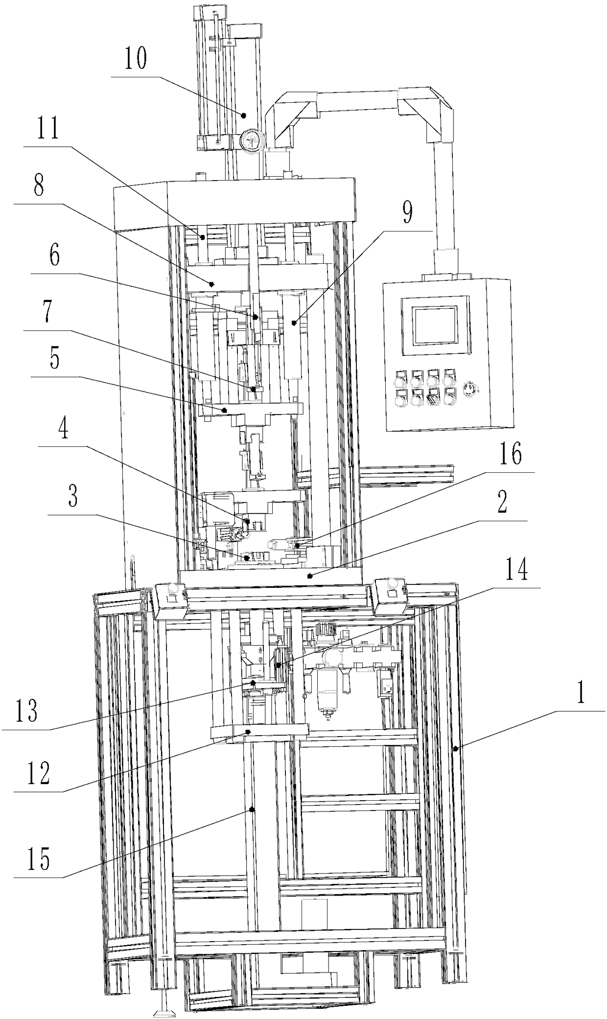
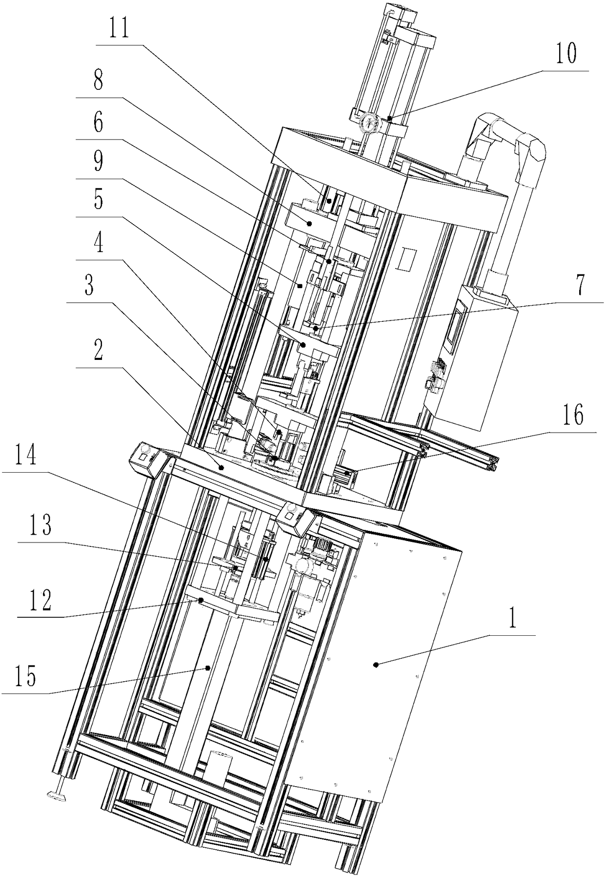
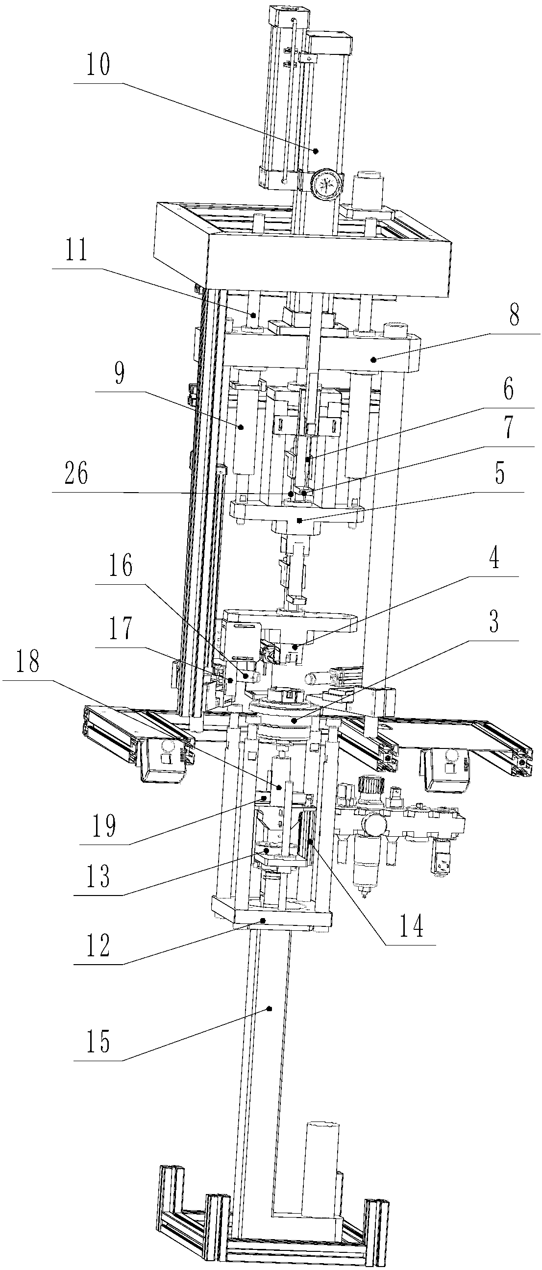
[0033] Such as Figure 1 to Figure 10 As shown, a motor rotor axial gap adjuster includes a frame 1, an operating platform 2 is provided on the frame 1, and a lower cavity 3 matching the front end cover 23 of the motor is fixed on the operating platform 2 The lower die 3 is provided with an insertion hole 33 to facilitate the insertion of the front end of the motor rotor shaft 22, and the lower die 3 is vertically slidably mounted with two symmetrically pressing the motor front end cover 23 to make it axial Deformed top pressure block 21.

[0034] Such as Picture 10 As shown, the figure shows a motor used for automobile cooling fans. The rear end of the rotor shaft 22 of the motor is mounted on the rear end cover through a rear bearing, and the rear end cover is fixed to the stator housing 24; and the front end of the rotor shaft 22 It penetrates through the front end cover 23 a...


PUM


Abstract

The present invention discloses a motor rotor axial clearance adjusting machine. The adjusting machine includes a rack and an operation platform. A lower female die is fixed on the operation platform. A top pressing block is vertically installed on the lower female die in a sliding manner. A lower slide seat is vertically installed on the rack in the sliding manner. A top pressing transmission piece is fixed on the lower slide seat. A lower ejector pin is vertically installed on the lower slide seat in the sliding manner. The lower ejector pin is driven by a lower ejector pin lifting power apparatus. An upper slide seat is vertically installed on the rack in the sliding manner. The upper slide seat is provided with an upper pressing die. The upper pressing die is provided with a through hole. An upper ejector pin is installed on the upper slide seat in the sliding manner. The upper ejector pin is corresponding to the rear end of a motor rotor shaft. The upper ejector pin is connected with a measuring mechanism for measuring an upper ejector pin moving distance. The clearance adjusting machine can rapidly perform axial clearance adjustment on each motor before the motor leaves the factory, thereby greatly improving clearance adjustment precision, improving efficiency, facilitating adjustment, being applicable to mass production, and ensuring product quality stability.

Description

Technical field [0001] The invention relates to a gap adjuster, in particular to a motor rotor axial gap adjuster. Background technique [0002] The cooling fan of the vehicle is driven by a motor. This motor has a rotor. The rotor shaft of the rotor is supported by bearings at the front and rear ends and installed on the end covers at both ends. The end of the motor’s rotor shaft protruding from the stator shell is the front end. One end of the rotor shaft is the back end, so the back end of the rotor shaft is rotatably mounted on the back end cover, and the front end of the rotor shaft penetrates the front end cover and is mounted on the front end cover through the bearing rotation, and the front end cover is clamped and fixed to the stator shell. The rotor has an armature composed of a coil with an iron core, and a segmented commutator for supplying current, and a sliding contact for power supply is provided on the commutator. The commutator is at the rear end of the rotor sh...

Claims


Application Information

Patent Timeline
Patent Type & Authority Patents(China)
IPC IPC(8): H02K15/02
CPCH02K15/024
Inventor 姚小君卢勇
Owner JIANGSU LANGXIN ELECTRIC
Why Eureka
Try Eureka