Automatic direction-regulating type permanent-magnet direct-drive wind driven generator

A wind turbine, permanent magnet direct drive technology, which is applied to wind turbines at right angles to the wind direction, wind turbines, wind turbine control and other directions, can solve the problem of low wind energy utilization, difficult to control stalls, and complex control structures for vertical axis fans. and other problems, to achieve the effect of improving the utilization rate of wind energy, simplifying the structure, and being easy to rectify and store.

Active Publication Date: 2016-06-15
HEBEI UNIVERSITY OF SCIENCE AND TECHNOLOGY
View PDF4 Cites 3 Cited by
  • Summary
  • Abstract
  • Description
  • Claims
  • Application Information

AI Technical Summary

Problems solved by technology

However, due to its complex control structure, it generally needs a gearbox, yaw system, etc., which is limited.
The control structure of the vertical axis fan is simple, it has the advantages of wide operating wind speed range, low starting wind speed, simple manufacturing process, low cost, various types of blades, and less noise pollution; however, the vertical axis fan has low wind energy utilization rate, is not easy to self-start, and is difficult to control stall
At present, these two types of fans have been extensively studied by scholars, and their respective models and ideas have been proposed, but both have limitations

Method used


Image

  • Automatic direction-regulating type permanent-magnet direct-drive wind driven generator
  • Automatic direction-regulating type permanent-magnet direct-drive wind driven generator
  • Automatic direction-regulating type permanent-magnet direct-drive wind driven generator

Examples


Embodiment Construction

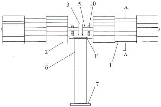
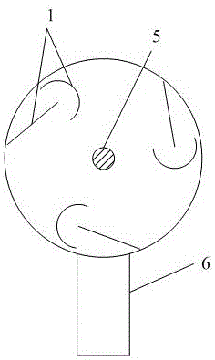
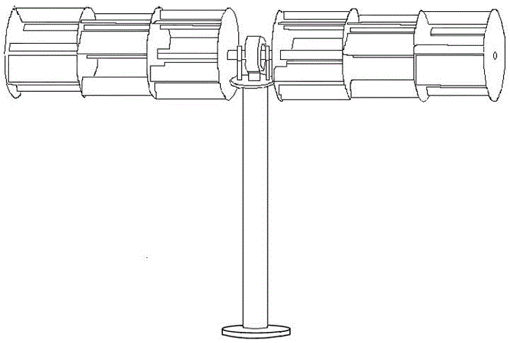
[0031] see attached Figure 1-14, The automatic direction-adjustable permanent magnet direct-drive wind generator is characterized in that it mainly includes: a generator 8, a horizontal main shaft or a rotating shaft 5, a bearing seat 10, a wind wheel 1, a bracket 6, an anemometer, a sensor, a control The generator 8 is installed on the upper end platform of the support 6, the middle of the horizontal main shaft or the rotating shaft (5) is fixed on the rotor of the generator 8, and a bearing seat 10 is provided on both sides of the generator 8, The horizontal main shaft or rotating shaft 5 is mounted on two bearing seats 10; both ends of the horizontal main shaft or rotating shaft 5 are symmetrically fixed with a wind wheel 1, and the wind wheel 1 has a Senegalese structure, that is, the wind wheel is composed of side by side. It is composed of more than 2 wind wheel sets, each wind wheel set includes 2 vertical discs, the center of the vertical disc is fixed on the horizont...


PUM


Abstract

The invention provides an automatic direction-regulating type permanent-magnet direct-drive wind driven generator, and relates to the technical field of wind driven generators. The automatic direction-regulating type permanent-magnet direct-drive wind driven generator comprises a power generator, wind wheels, a wind speed and wind direction measurer, a sensor, a controller and a storage battery, wherein the power generator is arranged on a platform at the upper end of the bracket; the two sides of the power generator are separately provided with a bearing base; a horizontal type main shaft is arranged on the bearing bases; the two end parts of the horizontal type main shaft are fixedly provided with wind wheels, and the wind wheels are of Senegal type structures; and a bearing is arranged between the platform at the upper end and a supporting column body. When the wind direction is not perpendicular to the horizontal type main shaft or exceeds a set value, the power generator can be in an electric state, so that the horizontal type main shaft deflects in a direction perpendicular to wind force until a perpendicular state, and the horizontal type main shaft is automatically recovered to a power generation state for generating power. According to the automatic direction-regulating type permanent-magnet direct-drive wind driven generator, the starting wind speed is low, the output torque is stable, the service life of a fan is long, the power generation efficiency is high, the structure is simple, and the space usage is less.

Description

technical field [0001] The patent of the present invention relates to the technical field of wind turbines. Background technique [0002] With the depletion of coal resources, there is an urgent need to find new clean and non-polluting energy sources to replace them in the field of power generation. Wind energy resources have the advantages of wide distribution, inexhaustible, inexhaustible, clean, etc., and have attracted the attention of scholars at home and abroad. At present, the horizontal axis fan is widely used, and the horizontal axis fan has the advantages of high utilization rate of wind energy and mature production and processing. However, due to its complex control structure, it generally requires a gearbox, a yaw system, etc., which is limited. The vertical axis fan has the advantages of simple control structure, wide operating wind speed range, low starting wind speed, simple manufacturing process, low cost, various blade types, and less noise pollution. sta...

Claims


Application Information

Patent Timeline
Patent Type & Authority Applications(China)
IPC IPC(8): F03D9/11F03D7/06F03D3/06F03D3/02F03D80/70H02K21/14H02K1/27
CPCF03D3/002F03D3/02F03D3/061F03D3/062F03D7/06F05B2270/329F05B2270/605H02K1/2753H02K1/2773H02K21/14H02K2201/03Y02E10/74Y02E70/30
Inventor 李争
Owner HEBEI UNIVERSITY OF SCIENCE AND TECHNOLOGY
Why Eureka
Try Eureka