Compact moving-iron telephone receiver,

A receiver, compact technology, applied in the direction of sensors, electrical components, etc., can solve problems such as troublesome application of end customers, achieve the effect of improving low-frequency sensitivity, reducing low-frequency distortion, and wide application range

Pending Publication Date: 2016-09-21
SUZHOU E AUDIO ELECTRONICS
View PDF0 Cites 1 Cited by
  • Summary
  • Abstract
  • Description
  • Claims
  • Application Information

AI Technical Summary

Problems solved by technology

However, in the current actual production of the receiver, the PCB board of the receiver is generally pasted at the end of the receiver. In the design of the enlarged rear cavity, the total length of the product will increase, and the PCB board at the end will make the total length of the product longer. , which will cause some trouble for end-customer applications

Method used


Image

  • Compact moving-iron telephone receiver,
  • Compact moving-iron telephone receiver,
  • Compact moving-iron telephone receiver,

Examples


Embodiment 1

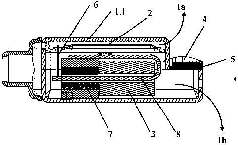
[0023] Such as figure 1 , 2 As shown, a compact moving iron receiver includes an electromagnetic shielding shell 1, a diaphragm 2, a coil 3, a PCB board 4, a connecting rod 6, a magnet 7, and a tongue 8. The electromagnetic shielding shell 1 is buckled together The upper cover 1.1 and the lower cover 1.2 are composed. The diaphragm 2 is fixed in the upper cover 1.1. The internal space of the electromagnetic shielding shell is divided into a front cavity 1a and a rear cavity 1b. The space formed between the diaphragm 2 and the top plate of the upper cover is the front cavity 1a The remaining space inside the electromagnetic shielding shell is the rear cavity 1b, the coil 3, the magnet 7, and the tongue reed 8 are arranged in the rear cavity 1b. One end of the connecting rod 6 is fixed at the end of the tongue 8 and the other end is connected to the diaphragm 2.

[0024] The width of the upper cover 1.1 and the lower cover 1.2 are the same. The front end of the upper cover 1.1 and t...

Embodiment 2

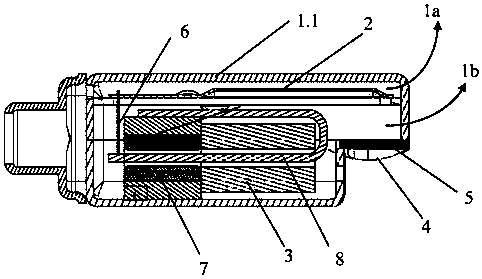
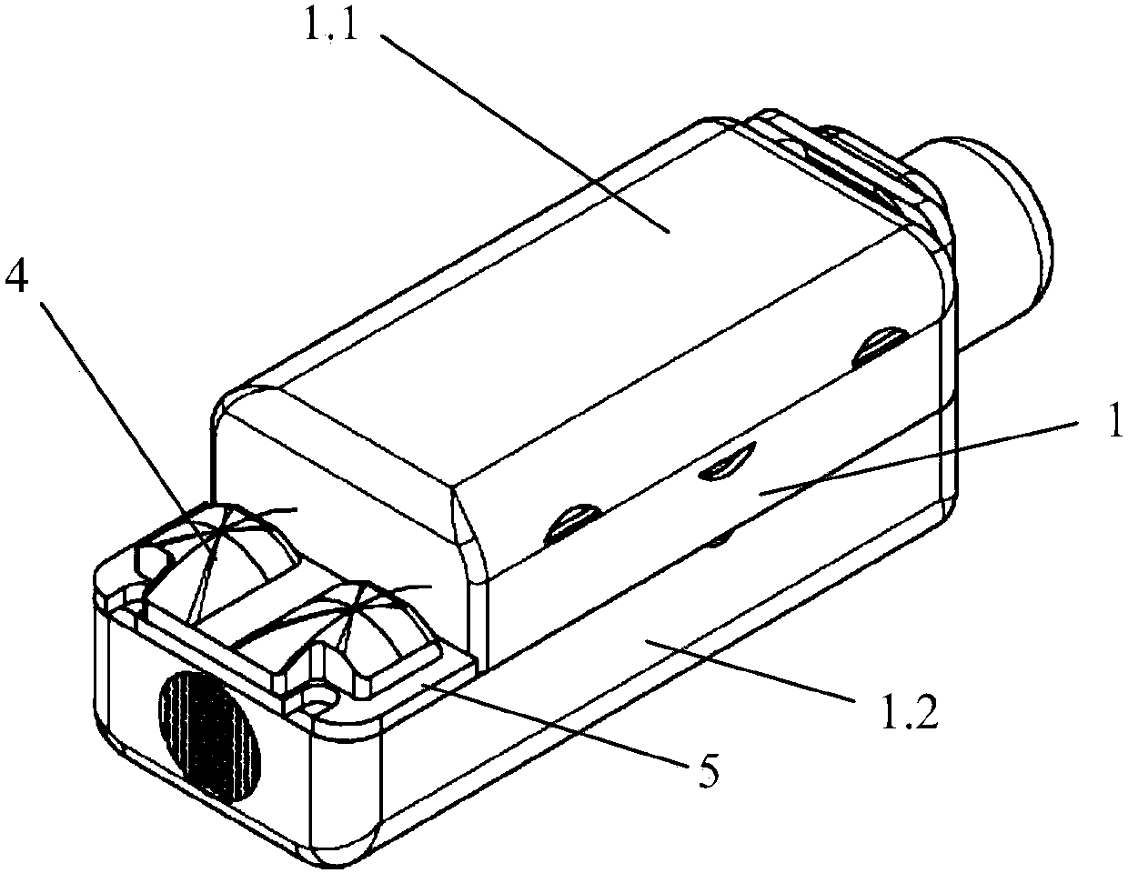
[0027] Such as image 3 , 4 As shown, a compact moving iron receiver includes an electromagnetic shielding shell 1, a diaphragm 2, a coil 3, a PCB board 4, a connecting rod 6, a magnet 7, and a tongue 8. The electromagnetic shielding shell 1 is buckled together The upper cover 1.1 and the lower cover 1.2 are composed. The diaphragm 2 is fixed in the upper cover 1.1. The internal space of the electromagnetic shielding shell is divided into a front cavity 1a and a rear cavity 1b. The space formed between the diaphragm 2 and the top plate of the upper cover is the front cavity 1a The remaining space inside the electromagnetic shielding shell is the rear cavity 1b, the coil 3, the magnet 7, and the tongue reed 8 are arranged in the rear cavity 1b. One end of the connecting rod 6 is fixed at the end of the tongue 8 and the other end is connected to the diaphragm 2.

[0028] The width of the upper cover 1.1 and the lower cover 1.2 is the same, the front end of the upper cover 1.1 and th...


PUM


Abstract

The invention discloses a compact moving-iron telephone receiver. The compact moving-iron telephone receiver comprises an electromagnetic shielding shell, a diaphragm, a coil and a PCB board. The compact moving-iron telephone receiver is characterized in that the electromagnetic shielding shell is composed of an upper cover and a lower cover which are buckled together. The diaphragm is fixed in the upper cover and is used for dividing the internal space of the electromagnetic shielding shell into a front cavity and a rear cavity. The space formed between the diaphragm and the top board of the upper cover is the front cavity. The residual space in the electromagnetic shielding shell is the rear cavity. The lengths of the rear ends of the upper cover and the lower cover are different. The rear ends of the upper cover and the lower cover are connected through a step surface. The PCB board is fixed on the step surface. The PCB board is moved out from the tail end of the product, and therefore, the internal space of the rear cavity is greater. Compared with the telephone receiver in the prior art, the compact moving-iron telephone receiver has the advantages that under the condition that the effective volumes of the rear cavities are the same, the external size of the product is enabled to be smaller, the telephone receiver can be applied to the smaller space, the application range is wide, and moreover, the quality of the telephone receiver is ensured.

Description

Technical field [0001] The invention designs a new type of receiver structure. Background technique [0002] The traditional moving iron receiver is a very efficient sound-producing component, mainly used as the sound output component of hearing aids, earphones and similar products. Working principle: Under the action of audio current, the reed in the magnetic field will move up and down, thus driving the vibrating diaphragm to vibrate up and down to produce sound. The sound response curve is the most basic and most critical technical indicator of the receiver. [0003] For music headphones made with moving iron receivers, in order to improve the sense of hearing, in the design of moving iron receivers, it is expected to increase the volume of the back cavity to increase the low frequency sensitivity in the response curve and reduce distortion. However, in the actual production of the receiver, the PCB board of the receiver is usually pasted on the end of the receiver. In the des...

Claims


Application Information

Patent Timeline
Patent Type & Authority Applications(China)
IPC IPC(8): H04R11/04
CPCH04R11/04
Inventor 薛洪明张春刚刘洋
Owner SUZHOU E AUDIO ELECTRONICS
Why Eureka
Try Eureka