Mechanically controlled electric power electrical cabinet

A technology for mechanical control and electrical cabinets, applied in the field of electrical cabinets, can solve problems such as lack of electrical cabinet devices, and achieve the effects of simple device structure, safe and reliable use, and convenient maintenance

Inactive Publication Date: 2016-09-21
深圳进源环保科技有限公司
View PDF2 Cites 4 Cited by
  • Summary
  • Abstract
  • Description
  • Claims
  • Application Information

AI Technical Summary

Problems solved by technology

In the prior art, there is also a lack of such an electrical cabinet device that takes into account both the mechanical connection locking function and the electrical connection function.

Method used


Image

  • Mechanically controlled electric power electrical cabinet
  • Mechanically controlled electric power electrical cabinet

Examples


Embodiment Construction

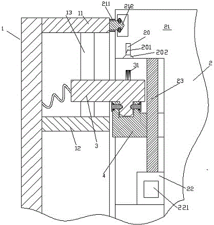
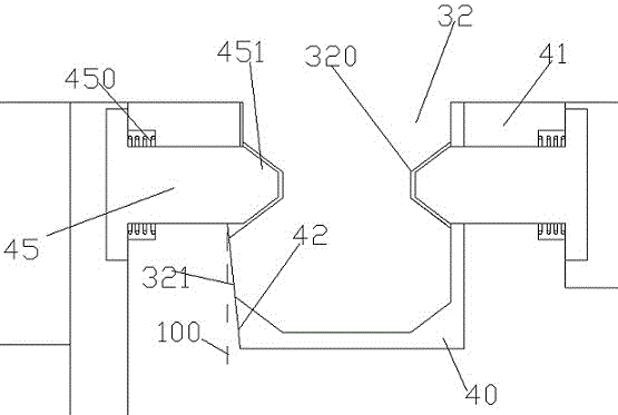
[0009] Combine below Figure 1-2 The present invention will be described in detail.

[0010] A mechanically controlled power electrical cabinet according to an embodiment of the present invention includes a cabinet main body 2 and an electrical cabinet cover 1 detachably covering the cabinet main body 2 through a clip 212, wherein the electrical cabinet The cover body 1 includes an upper transverse wall 11 arranged on the upper side and a lower transverse wall 12 located below the upper transverse wall 11 , between the upper transverse wall 11 and the lower transverse wall 12 there is a support for guiding the locking and power supply slider 3 The guide rod 13, the cabinet main body 2 includes a top wall 21 for engaging the upper transverse wall 11 and receiving the chuck 212, the lower side of the top wall 21 is provided with a cover body power supply socket 20 for connecting with the The lock is pluggably engaged with the electrical connection pin 31 at the upper side of th...


PUM


Abstract

Provided is a mechanically controlled electric power electrical cabinet, comprising a main body portion (2) and an electrical cabinet cover (1) detachably covering the main body portion (2) through a chuck (212), wherein the electrical cabinet cover (1) comprises an upper transverse wall (11) arranged on the upper side, and a lower transverse wall (12) arranged under the upper transverse wall (11); a guide rod (13) used for guiding a locking and power supply slide (3) is supported between the upper transverse wall (11) and the lower transverse wall (12); the main body portion (2) comprises a top wall (21) used for joining the upper transverse wall (11) and receiving the chuck (212).

Description

technical field [0001] The invention relates to the field of electrical cabinets. Background technique [0002] In an electrical cabinet, it often has a main body and a cover for closing and opening said main body. In addition to being used for physical coverage, the cover also has the function of operating and displaying internal information parameters. Therefore, besides being detachable, such a cover often needs to be powered to realize functions such as electrical parameter display and electrical operation. [0003] Some existing electrical cabinets are often difficult to unify the electrical connection performance with the complete disassembly function. Moreover, the completely disassembled cover needs to have a mechanical locking function to prevent it from being separated from the main body due to misoperation because it may completely break away from the main body during operation. The prior art also lacks such an electrical cabinet device that takes into account ...

Claims


Application Information

Patent Timeline
IPC IPC(8): H05K5/02H01R13/629
CPCH01R13/629H05K5/0247
Inventor 萧莠捷
Owner 深圳进源环保科技有限公司
Why Eureka
Try Eureka