
Electric shoe mold used by being matched with disposal slipper

A disposable, electric shoe technology, applied in footwear, applications, clothing, etc., can solve the problems of no thickness, uncomfortable wearing, inconvenient to use, etc., to achieve the effect of not easy to slap feet, avoid cross infection, and easy to replace

Inactive Publication Date: 2016-09-28
张亚东
View PDF7 Cites 0 Cited by
  • Summary
  • Abstract
  • Description
  • Claims
  • Application Information

AI Technical Summary

Problems solved by technology

However, although disposable non-woven slippers solve the risk of infectious diseases, they also have many defects: because they are disposable slippers, the soles and uppers of the slippers are made of less materials, which leads to the loss of soles and uppers. are very thin
[0004] Because the upper of the disposable slippers is very thin, the upper is easy to collapse and attach to the sole. When wearing it, guests need to stretch it with their hands to put it on. It is very inconvenient to use, especially when the lights are not turned on at night. It is not easy to wear, and the upper of the disposable slippers is not strong enough, it is easy to tear when worn, causing the shoes to break and cannot be worn again
[0005] Because the sole of disposable slippers is also very thin, there is no sense of thickness and lack of elasticity when wearing, and it is uncomfortable to wear. In addition, because the sole is relatively thin, customers will easily walk unsteadily when wearing it, and it will be very uncomfortable to walk in uneven places. Feet, causing swelling and pain of the feet. When used in cold seasons, the soles of the feet feel cold, uncomfortable or even frozen
When wearing and walking on flat ground, because the friction coefficient of the sole of disposable slippers is relatively small, the sole becomes more slippery after being wetted with water, and it is easy for customers to slip and fall, so it is not suitable for wet and slippery places such as toilets and bathrooms. Wear and walk around the venue

Method used


Image

  • Electric shoe mold used by being matched with disposal slipper
  • Electric shoe mold used by being matched with disposal slipper
  • Electric shoe mold used by being matched with disposal slipper

Examples


Embodiment Construction

[0025] The following description and drawings illustrate specific embodiments of the invention sufficiently to enable those skilled in the art to practice them. The examples merely represent possible variations. Individual components and functions are optional unless explicitly required, and the order of operations may vary. Portions and features of some embodiments may be included in or substituted for those of other embodiments. The scope of embodiments of the present invention includes the full scope of the claims, and all available equivalents of the claims. These embodiments of the present invention may be referred to herein, individually or collectively, by the term "invention", which is for convenience only and is not intended to automatically limit the application if in fact more than one invention is disclosed The scope is any individual invention or inventive concept. That is to say, there may be more than one embodiment in the present invention, and there may be ...


PUM


Abstract

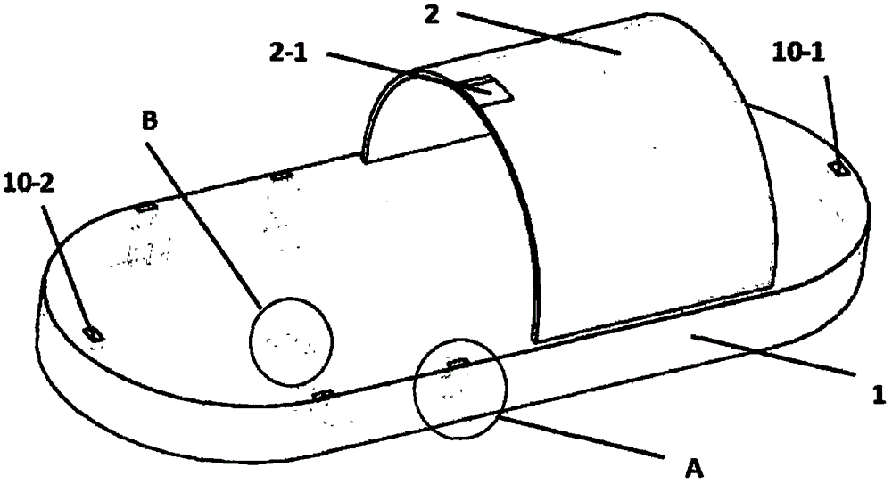
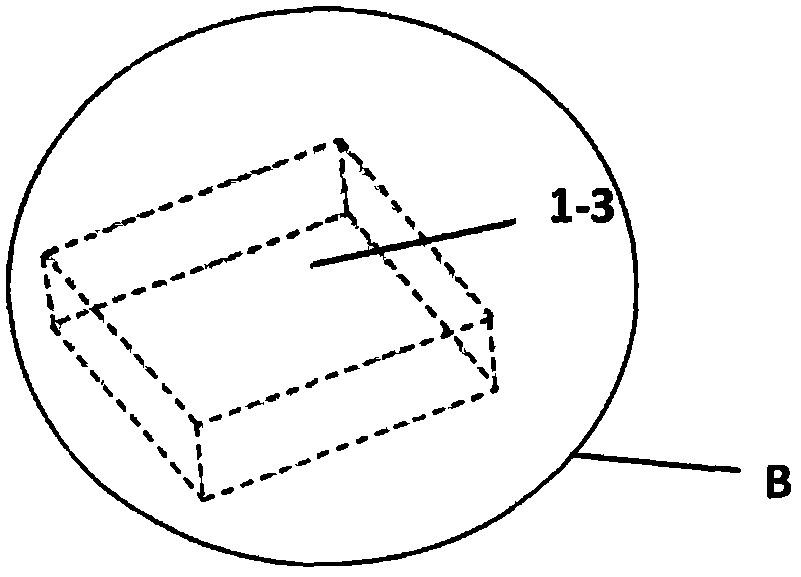
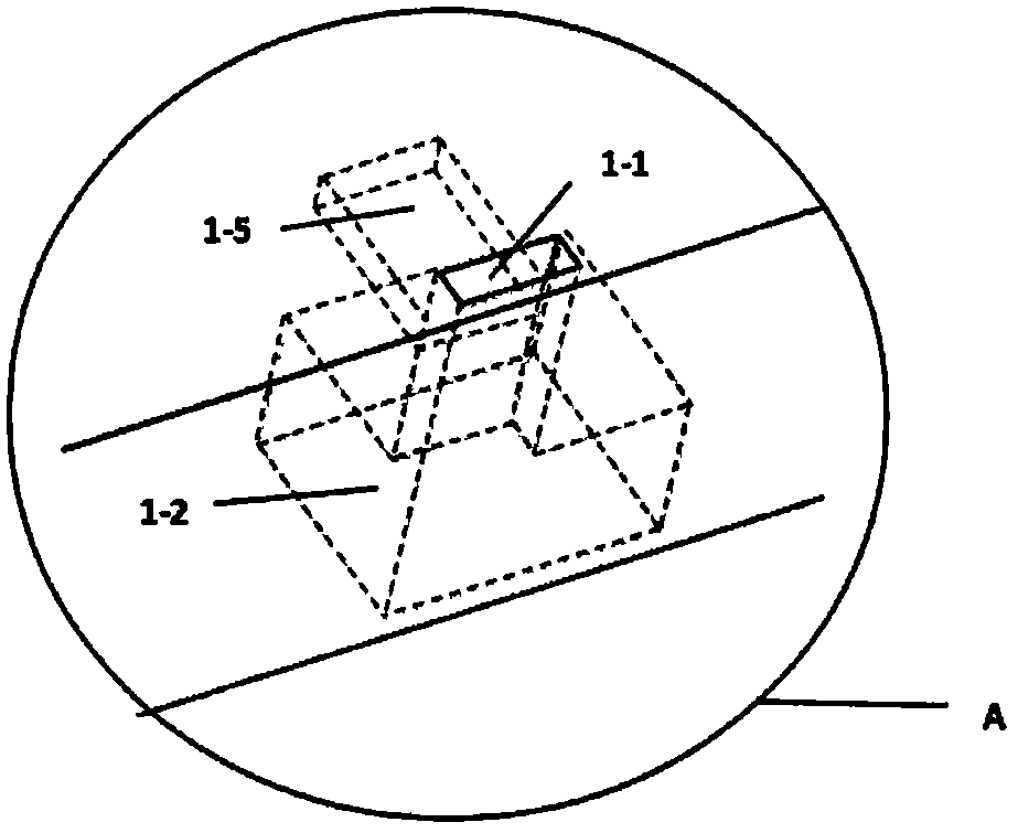
The invention discloses an electric shoe mold used by being matched with a disposal slipper. The structure of the electric shoe mold comprises a shoe sole (1) and a shoe upper (2). The electric shoe mold is characterized in that the two sides of the heel portion of the shoe sole (1) are each provided with at least one rack hole (1-1), a micro electromotor groove (1-2) and a magnet groove (1-5) are arranged in each rack hole (1-1), a power supply groove (1-3) is formed in the shoe sole (1), at least two photoelectric sensors are arranged on the front portion and the back portion of the shoe sole (1), a shoe upper groove (2-1) is formed in the surface of the side, close to the heel, of the shoe upper (2), shoe sole fixing devices (4) are arranged in the rack holes (1-1), the shoe upper groove (2-1) is matched with a shoe upper fixing device (3), micro gears (6) and micro electromotors (5) are installed in the micro electromotor grooves (1-2), a battery (7) is arranged in the power supply groove (1-3), and magnets (9) are arranged in the magnet grooves (1-5). The electric shoe mold is very convenient to use and comfortable.

Description

technical field [0001] The invention relates to a shoe mold, in particular to an electric shoe mold which can be used with disposable slippers. Background technique [0002] People go to take a bath or go out to stay in hotels and guesthouses and generally do not bring their own slippers to use. Due to the large passenger flow in bathing centers, bathhouses, hotels and other places, slippers are frequently used. In order to serve guests well and meet their needs, hotels, hotels, bathing centers and other places will prepare slippers for customers. There are plastic slippers that are used repeatedly. The plastic slippers used have the risk of infecting beriberi and other infectious diseases. Even though the bathing center has done very strict disinfection treatment, customers still have concerns and worries when using them. In order to prevent customers' feet from being infected by bacteria Infection, and better service to guests, so most places such as hotels, guesthouses, ...

Claims


Application Information

Patent Timeline
Patent Type & Authority Applications(China)
IPC IPC(8): A43B3/20A43B3/00
CPCA43B3/20A43B3/34
Inventor 张亚东
Owner 张亚东
Learn More