Perforating machine for manifold

A punching machine and manifold technology, applied in the field of manifolds, can solve the problems of inability to automatically clamp, reduce work efficiency, increase labor force, etc., and achieve the effects of avoiding accidental injury, improving work efficiency, and reducing labor force.

Active Publication Date: 2016-09-28
无锡德斯凯动力科技有限公司
View PDF6 Cites 4 Cited by
  • Summary
  • Abstract
  • Description
  • Claims
  • Application Information

AI Technical Summary

Problems solved by technology

In the actual application of the manifold, it is necessary to process and punch the manifold. At this time, people often use a punching machine. The punching machines on the market, when punching the manifold, are all done manually. Clamping the manifold to punch holes cannot be clamped automatically, and the fittings are clamped manually, which increases labor and reduces work efficiency, and when clamping manually, there will be certain risks, resulting in accidental damage

Method used


Image

  • Perforating machine for manifold

Examples


Embodiment Construction

[0012] The technical solutions in the embodiments of the present invention will be clearly and completely described below in conjunction with the accompanying drawings in the embodiments of the present invention. Obviously, the described embodiments are only a part of the embodiments of the present invention, rather than all the embodiments. Based on the embodiments of the present invention, all other embodiments obtained by those of ordinary skill in the art without creative work shall fall within the protection scope of the present invention.

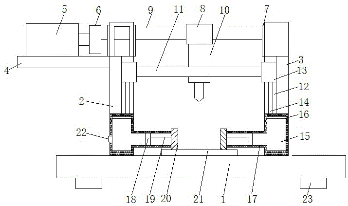
[0013] See figure 1 , The present invention provides a technical solution: a punching machine for manifolds, including a base 1, fixedly connected with a support block 23 through the bottom of the base 1, and the number of the support block 23 is not less than four, increase the punch The stability of the machine 10, the top of the base 1 is fixedly connected with a symmetrical first support rod 2 and a second support rod 3, through the ...


PUM


Abstract

The invention discloses a perforating machine for a manifold. The perforating machine comprises a base, wherein a first support bar and a second support bar which are mutually symmetrical are fixedly connected with the top of the base; one side surface of the first support bar is fixedly connected with a support plate; a motor is arranged at the top of the support plate; the output end of the motor is fixedly connected with an eccentric wheel; a rotary disc is arranged on one side surface of the second support bar; a bearing is arranged between the first support bar and the second support bar; the interior of the bearing is fixedly connected with a connecting bar; one end of the connecting bar extends to one side surface of the bearing and is fixedly connected with the rotary disc; and the other end of the connecting bar extends to the other side surface of the bearing, penetrates the first support bar and is fixedly connected with the eccentric wheel. The perforating machine for the manifold can achieve perforating without manually clamping the manifold by hand and can automatically clamp the manifold, thereby reducing the labor force, improving the working efficiency, lowering the operation risks and avoiding accidental injuries.

Description

Technical field [0001] The invention relates to the technical field of manifolds, in particular to a punching machine for manifolds. Background technique [0002] Manifolds are divided into intake manifolds and exhaust manifolds. The intake manifold is connected to the cylinder block of the engine. The exhaust of each cylinder is collected and led to the exhaust manifold, with branched pipelines. The main requirement for it is to reduce the exhaust resistance as much as possible and avoid interference between the cylinders. When the exhaust is too concentrated, the cylinders will interfere with each other, that is, when a cylinder is exhausted, it just hits another. Exhaust gas that is not exhausted from the cylinders will increase the resistance of the exhaust, thereby reducing the output of the engine. The solution is to separate the exhaust of each cylinder as much as possible, with one branch per cylinder, or one branch for two cylinders. In the actual use of the manifold, i...

Claims


Application Information

Patent Timeline
Patent Type & Authority Applications(China)
IPC IPC(8): B21D28/34B21D28/28B21D43/00
CPCB21D28/28B21D28/34B21D43/003
Inventor 华珍
Owner 无锡德斯凯动力科技有限公司
Why Eureka
Try Eureka