
Positioning method of left rear side face vehicle door inner plate assembly

A positioning method and assembly technology, applied to doors, vehicle parts, transportation and packaging, etc., can solve the problems of cumbersome, cumbersome, and many processes in the production process, and achieve the effect of improving production efficiency and reducing positioning processes

Active Publication Date: 2016-09-28
安徽大洋机械制造有限公司
View PDF5 Cites 0 Cited by
  • Summary
  • Abstract
  • Description
  • Claims
  • Application Information

AI Technical Summary

Problems solved by technology

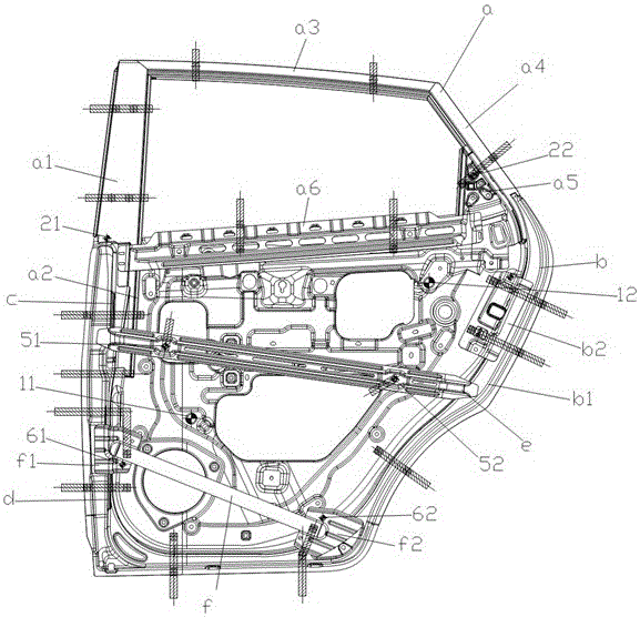
The existing production process of the left rear side door inner panel assembly is rather cumbersome, mainly through one-to-one assembly of each component of the left rear side door inner panel assembly and then one-time welding of each component, which is easy to exist. There is a problem of large fit gap or tight fit among the components, which is not conducive to the further processing of the left rear side door inner panel assembly and the left rear side door outer panel, resulting in waste products of the left rear side door. In order to improve the process Accuracy, including welding the door B-pillar a1, glass lift guide rail a2, upper strip a3, door C-pillar a4, triangular window panel a5, and outer panel reinforcement plate a6 into the upper frame assembly, and the anti-collision bar and the anti-collision bar The front and rear connecting plates f1 and f2 at both ends of the front and rear are first welded into the anti-collision bar assembly, so that the existing method of positioning each part of the left rear side door inner panel assembly one by one has more processes and is more complicated. It is cumbersome. In order to adapt to the new process of the left rear side door inner panel assembly, a simple and convenient positioning method for the left rear side door inner panel assembly needs to be developed to reduce the positioning process and improve production efficiency.

Method used


Image

  • Positioning method of left rear side face vehicle door inner plate assembly
  • Positioning method of left rear side face vehicle door inner plate assembly

Examples


Embodiment Construction

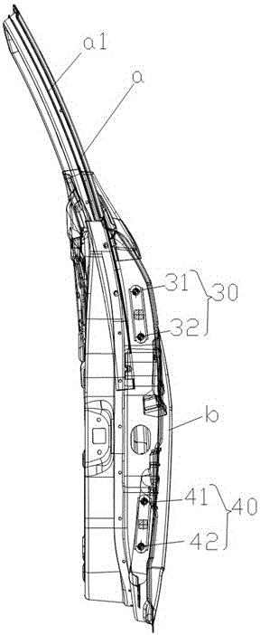
[0016] With reference to the accompanying drawings, a method for positioning the inner panel assembly of the left rear side door includes the following steps:

[0017] 1) Locate the door inner panel assembly b: place the door inner panel assembly b on the lower mold, and set the two door inner panel positioning pins 11, 12 on the lower mold, and the two door inner panel positioning pins 11, 12 The connection direction and the transverse direction of the door inner panel assembly b are arranged at an angle. The door inner panel assembly b is located at the positions of the positioning pins 11 and 12 of the two door inner panels. The holes are arranged correspondingly to the positioning pins 11 and 12 of the inner panels of the two doors;

[0018] 2) Position the upper frame assembly a: place the upper frame assembly a on the door inner panel assembly b, and set the lower mold on the position of the door B-pillar a1 and the triangular window panel a5 where the upper frame assemb...


PUM


Abstract

The invention relates to a positioning method of a left rear side face vehicle door inner plate assembly. The method includes the following steps of positioning the vehicle door inner plate assembly, positioning an upper frame assembly, positioning an upper nut plate and a lower nut plate, positioning an outer plate supporting plate, and positioning a bumper bar assembly. The process of positioning all parts of an existing left rear side face vehicle door inner plate assembly one by one is changed into the process of sequentially positioning the vehicle door inner plate assembly, the upper frame assembly, the upper nut plate, the lower nut plate, the outer plate supporting plate and the bumper bar assembly, the positioning procedures of the left rear side face vehicle door inner plate assembly are reduced, and production efficiency is greatly improved.

Description

technical field [0001] The invention belongs to the field of vehicle production and manufacturing, relates to the production and manufacture of small and micro cars, and in particular relates to a positioning method for a left rear side door inner panel assembly. Background technique [0002] The left rear side door is tooled through a series of processes of hemming, gluing, and electric welding on the left rear side door inner panel assembly and the left rear side door outer panel. refer to figure 1 , the left rear side door inner panel assembly mainly includes door B-pillar a1, glass lift guide rail a2, upper strip a3, door C-pillar a4, triangular window panel a5, outer panel reinforcement a6, door inner panel b1, lock body reinforcement b2, outer plate support plate e, upper and lower nut plates c, d, anti-collision bar, anti-collision bar front and rear connecting plates f1, f2 and a series of structural parts. The existing production process of the left rear side door...

Claims


Application Information

Patent Timeline
IPC IPC(8): B60J5/04
CPCB60J5/0413B60J5/0423B60J5/0463B60J5/0468
Inventor 倪勤梅谢碧
Owner 安徽大洋机械制造有限公司
Learn More