Rapier loom edge fabric yarn guide device

A technology of rapier looms and yarn guide devices, which is applied in the fields of looms, textiles, textiles, and papermaking. It can solve the problems of reduced warp tension of waste edges, reduce breakage, improve the quality of waste edges, and prevent tension from breaking Effect

Active Publication Date: 2016-09-28
ZHEJIANG FAMOUS TEXTILE CO LTD
View PDF10 Cites 6 Cited by
  • Summary
  • Abstract
  • Description
  • Claims
  • Application Information

AI Technical Summary

Problems solved by technology

[0012] The purpose of the present invention is to provide a side cloth yarn guide device for rapier looms, which solves the problem that it needs to be wound on the waste side tube before use, and the tension of the waste side warp will become smaller with the use of the waste side yarn , with the advantages of balanced warp tension and not easy to break

Method used


Image

  • Rapier loom edge fabric yarn guide device
  • Rapier loom edge fabric yarn guide device
  • Rapier loom edge fabric yarn guide device

Examples


Embodiment 1

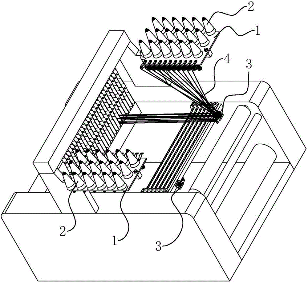
[0052] Embodiment 1: A kind of side cloth guide device of rapier loom, such as figure 1 As shown, it includes a creel platform 1 and a threading plate 3, and the threading plate 3 is provided with several yarn guide holes; the creel platform 1 is arranged horizontally, and a connecting rod 12 is fixedly connected to the bottom of the creel platform 12, and one end of the connecting rod 12 protrudes from the creel platform 1 It is rotatably connected with a support 5, and the support 5 is fixedly connected on the rapier loom by bolts.

[0053] refer to figure 2 , A number of through holes are arranged on the creel platform 1, and the through holes are arranged in an array. In this embodiment, the through holes are arranged in three rows, and the number of each row is six. Wherein, a yarn rod 11 is inserted into each through hole, and the surface of the yarn rod 11 is provided with external threads, which are clamped and fixed on the creel platform 1 by two nuts respectively l...

Embodiment 2

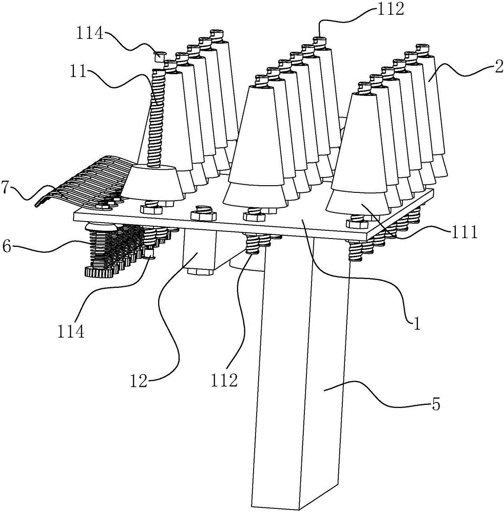
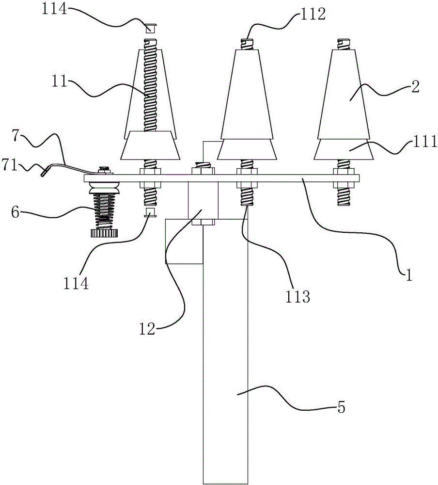
[0062] Embodiment 2: as Figure 5 and Figure 6 As shown, the difference from Embodiment 1 is that an oiling mechanism is also provided at the bottom end of the creel table 1, and the oiling mechanism is located between the two rows of yarn rods 11 near the tension regulator 6, and the oiling mechanism includes The oil pot 84 and the oil core inserted in the oil pot 84 are connected with the wool felt 81 between the oil core and a discharge yarn opening 113 close to the tension regulator 6 .

[0063] Among them, refer to Figure 7 , Figure 8 and Figure 10 One end of the wool felt 81 is connected with a felt belt 82, and the two ends of the felt belt 82 are integrally connected to the wool felt 81 to form a ring structure, and an elastic belt is connected to the felt belt 82, and the elastic belt and the felt belt 82 form a circular collar. The shape collar is set on the yarn outlet 113 of the yarn rod 11 to realize the connection between the wool felt 81 and the yarn out...


PUM


Abstract

The invention discloses a rapier loom edge fabric yarn guide device which comprises a creel platform and a threading plate. The creel platform is horizontally arranged, multiple yarn bars used for inserting cheeses are arranged on the upper end face of the creel platform, the bottom ends of the yarn bars penetrate through the creel platform, hollow yarn guiding channels are formed in the yarn bars, a yarn inlet is formed by each yarn guiding channel at the vertex of the corresponding yarn bar, and a yarn outlet is formed in the portion, on the lower portion of the creel platform, of the bottom end of each yarn bar; tension-regulating devices are arranged on the edges of the lower end face of the creel platform, one side, provided with the tension-regulating devices, of the creel platform extends to form elastic flakes, the number of the tension-regulating devices and the number of the elastic flakes are the same as the number of the yarn bars, and yard guides are arranged at the ends of the elastic flakes; waste selvage yarns penetrate through the hollow yarn guiding channels and then sequentially pass through the tension-regulating devices, the yarn guides and the threading plate, the problems that before the device is used, the waste selvage yarns need to be wound on a waste selvage cylinder in advance, and tension of waste selvage warp becomes small with usage of the waste selvage yarns are solved, and the advantages that the tension of the waste selvage warp is balanced, and the waste selvage warp is not prone to breaking are achieved.

Description

technical field [0001] The invention relates to the field of textile equipment, in particular to a side cloth yarn guide device of a rapier loom. Background technique [0002] When weaving a high-density fabric, the larger the cover factor is, the larger the cloth fell is moved toward the delivery side of the warp compared to the reed portion. As a result, the following problems arise: [0003] 1. The phenomenon that the fabric near the weaving fell hits the weft, and it is difficult to obtain the fabric with the desired weft density; [0004] 2. When the speed of the loom is increased, the amount of movement of the fell of the selvedge portion to the delivery side of the warp becomes larger than that of the reed portion more significantly. Since the warp in the selvage portion is slack, a difference in cloth length between the selvedge portion and the center portion occurs, resulting in a wave phenomenon in the selvage portion. The fabric is cut and sewn to form a desire...

Claims


Application Information

Patent Timeline
Patent Type & Authority Applications(China)
IPC IPC(8): D03D47/40
CPCD03D47/40
Inventor 汤建方高卫中张平曹刚
Owner ZHEJIANG FAMOUS TEXTILE CO LTD
Why Eureka
Try Eureka