
Thread trimming mechanism of sewing machine

A thread-cutting mechanism and sewing machine technology, which are applied to the thread-cutting mechanism, sewing machine components, sewing equipment and other directions in the sewing machine, can solve the problems of instability, residual thread length, increase the manual thread trimming process, etc., and achieve the effect of position stability.

Active Publication Date: 2016-09-28
JACK SEWING MASCH CO LTD
View PDF5 Cites 21 Cited by
  • Summary
  • Abstract
  • Description
  • Claims
  • Application Information

AI Technical Summary

Problems solved by technology

[0003] The stitches of the sewing machine are formed by the mutual movement of the needle and the rotary hook. In order to ensure that the suture does not touch the thread trimming edge under normal sewing conditions and does not affect the movement of the needle and the rotary hook, the movable knife and the fixed knife must be To avoid the movement range of the movable part, the fixed knife is fixed on one side of the needle center, resulting in a certain distance between the fixed knife and the machine needle center, and there is also a certain distance between the overlapping position of the movable knife and the fixed knife edge and the machine needle, and The overlapping position of the blades will also change due to various reasons such as installation, so that the remaining thread ends on the sewn product after thread trimming are too long and unstable, and the length of the remaining thread ends left on the needle side is unstable.
Long thread residues on the sewn product need to be manually trimmed; thread residues of unstable length on the needle will cause the needle to form bad stitches before the next sewing, affecting the quality of the sewn product

Method used


Image

  • Thread trimming mechanism of sewing machine
  • Thread trimming mechanism of sewing machine
  • Thread trimming mechanism of sewing machine

Examples


Embodiment 1

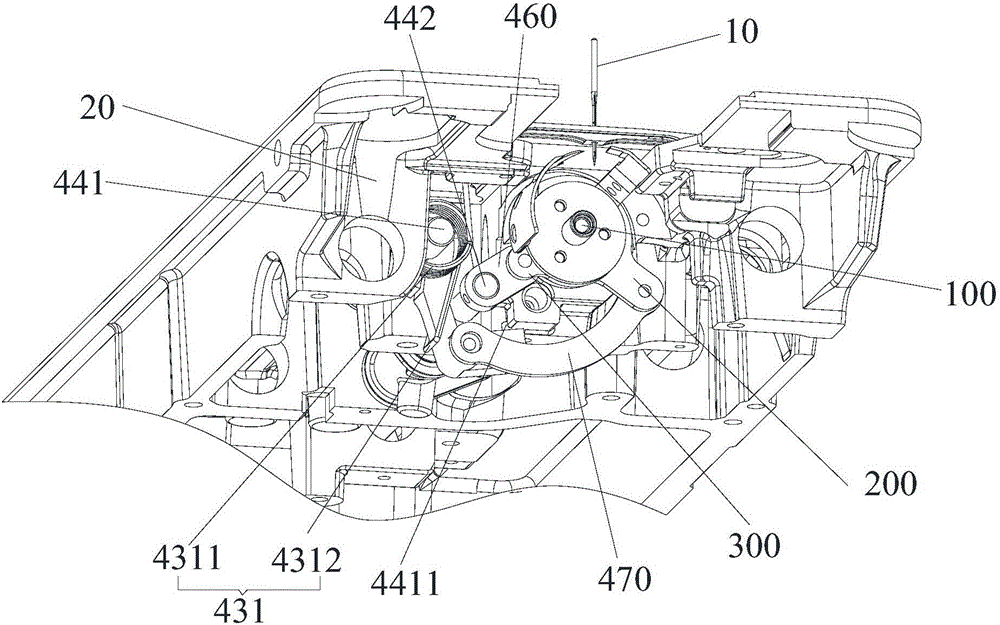
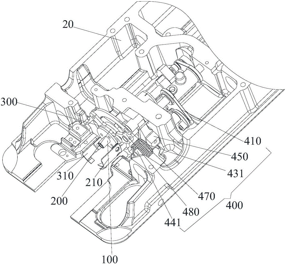
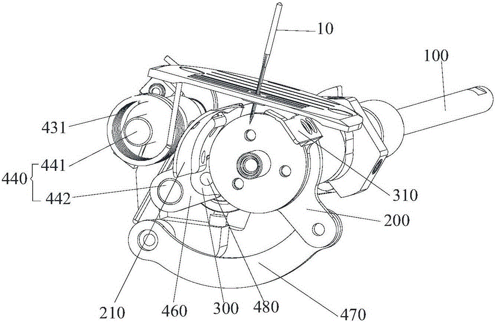
[0066] Such as Figure 1 to Figure 5 and Figure 7 As shown, the thread trimming mechanism of the sewing machine of the present embodiment is provided with a rotating shaft 100 in the casing of the sewing machine, and the thread trimming mechanism includes:

[0067] The main tool holder 200, the auxiliary tool holder 300 and the driving mechanism 400 arranged in the casing;

[0068] The main movable knife 210 is installed on the main knife rest 200; the auxiliary movable knife 310 is installed on the auxiliary knife rest 300;

[0069] The output end of the driving mechanism 400 is connected with the main crank 450 and the auxiliary crank 460, the main crank 450 is connected with the main tool rest 200, and the auxiliary crank 460 is connected with the auxiliary tool rest 300;

[0070] The output end of the drive mechanism 400 rotates reciprocatingly; the drive mechanism 400 drives the main tool rest 200 to reciprocate around the rotation axis 100 through the main crank 450, ...


PUM


Abstract

The invention provides a thread trimming mechanism of a sewing machine. A rotating shaft is arranged in a case of the sewing machine. The thread trimming mechanism comprises a main tool rest, an auxiliary tool rest and a driving mechanism which are arranged in the case, wherein a main moving cutter is mounted on the main tool rest; an auxiliary moving cutter is mounted on the auxiliary tool rest; an output end of the driving mechanism is connected with a main crank and an auxiliary crank, the main crank is connected with the main tool rest, and the auxiliary crank is connected with the auxiliary tool rest; the output end of the driving mechanism performs reciprocating rotation; the driving mechanism drives the main tool rest to perform reciprocating rotation around the rotating shaft through the main crank and drives the auxiliary tool rest to perform reciprocating rotation around the rotating shaft through the auxiliary crank, so that the main moving cutter and the auxiliary moving cutter move face to face to complete close cutting and move back to back to complete resetting. The driving mechanism is adopted to drive the main crank and the auxiliary crank simultaneously so as to drive the main moving cutter and the auxiliary moving cutter to move oppositely around the rotating shaft for engagement, trimming of opposite threads and bottom threads is completed, and the engaged position of trimmed threads is stable.

Description

technical field [0001] The invention relates to the technical field of sewing machines, in particular to a thread trimming mechanism of a sewing machine. Background technique [0002] The thread trimming structure of the existing sewing machine is a movable knife and a fixed knife located under the needle plate and above the rotary hook. The fixed knife is fixed on the sewing machine base, and the movable knife rotates after being driven by a driving mechanism. The knife bite cuts the suture. [0003] The stitches of the sewing machine are formed by the mutual movement of the needle and the rotary hook. In order to ensure that the suture does not touch the thread trimming edge under normal sewing conditions and does not affect the movement of the needle and the rotary hook, the movable knife and the fixed knife must be To avoid the movement range of the movable part, the fixed knife is fixed on one side of the needle center, resulting in a certain distance between the fixed...

Claims


Application Information

Patent Timeline
IPC IPC(8): D05B65/00
CPCD05B65/00
Inventor 万义明潘建国管建平黄敏
Owner JACK SEWING MASCH CO LTD
Learn More