
A Digital Holographic Microscopy Method Based on Pixel Polarizer Array

A technology of digital holographic microscopy and pixel polarizer, which is applied in the direction of instruments, measuring devices, optical devices, etc., can solve the problems of not being able to observe with living cells, redundant time-consuming, and reduced resolution of reconstructed images, so as to improve efficiency As well as resolution, reducing the cumbersomeness of use, overcoming the effects of position matching and grayscale correction

Active Publication Date: 2019-02-12
UNIV OF SCI & TECH OF CHINA
View PDF4 Cites 0 Cited by
  • Summary
  • Abstract
  • Description
  • Claims
  • Application Information

AI Technical Summary

Problems solved by technology

[0006] In addition, the reconstruction algorithm of the traditional method is redundant and time-consuming, and the reconstructed image contains zero-order and plus-minus first-order diffraction images, so the resolution of the reconstructed image will be reduced when the zero-order and negative-order conjugate images are separated
Although the traditional four-step phase shift method can eliminate zero-order spots formed in the interference optical path, it is only suitable for digital holographic reconstruction of static objects and cannot be used for live cell observation

Method used


Image

  • A Digital Holographic Microscopy Method Based on Pixel Polarizer Array
  • A Digital Holographic Microscopy Method Based on Pixel Polarizer Array
  • A Digital Holographic Microscopy Method Based on Pixel Polarizer Array

Examples


Embodiment example 1

[0066] Implementation Cases 1. Based on the above-mentioned technical principles of the invention, the following are specific implementation cases. The measurement sample is a small opaque thin plate with the word "light" written on it, and the area where the word "light" is located is transparent. Experimental light path diagram as Figure 5 shown. After beam expansion and collimation, the laser light emitted by the laser is irradiated on the polarization beam splitter 1, and is divided into two beams of linearly polarized light perpendicular to each other. A beam forwardly passes through the non-polarizing beamsplitter prism 1 and irradiates as Figure 6 (a) On the measurement sample, the object light information is carried through the sample. Another beam of linearly polarized light is reflected by the polarization beam splitter 1, the objective lens and the non-polarization beam splitter 2 respectively to become the reference light. The object light and reference light...


PUM


Abstract

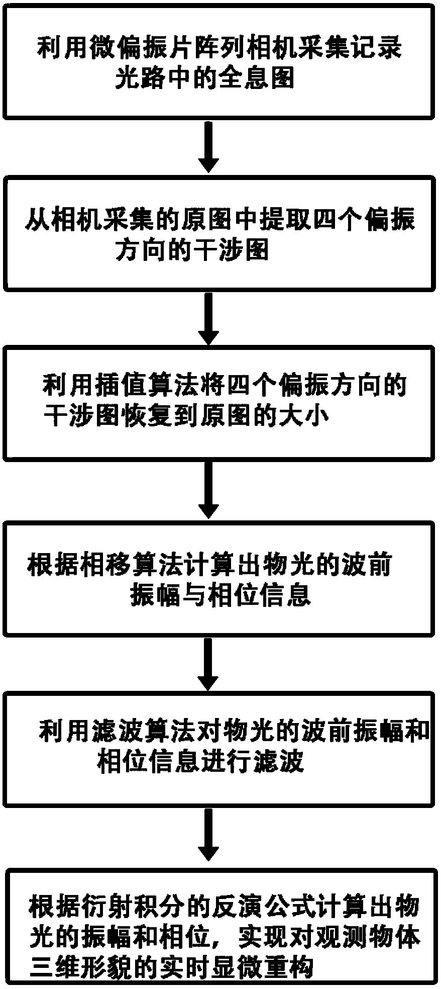
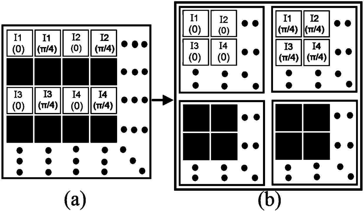
The invention relates to a digital holographic microscopy method based on a pixel polarizer array. A micro polarizer array camera used as a phase shifter in a phase-shifting polarized light path and a photosensitive element are used for recording a hologram formed by interference between object light and reference light; interferograms in four polarization directions are extracted from the hologram recorded and acquired by the micro polarizer array camera; an interpolation method such as linear interpolation is used for restoring the extracted interferograms in four polarization directions to the size of the original hologram, thereby avoiding resolution loss; the interferograms in four polarization directions and a phase-shifting interference algorithm are used for calculation to obtain an object light wave front amplitude diagram and a phase diagram; a filtering algorithm is used for filtering the object light wave front amplitude and the phase, and noise is eliminated; and according to an inversion algorithm for a diffraction integral, the object light wave front amplitude diagram and the phase diagram are used for realizing real-time microscopic reconstruction on the three-dimensional topography of an observed object.

Description

technical field [0001] The present invention belongs to or relates to the field of microscopic imaging of tiny objects such as cells. Specifically, the present invention proposes a method for real-time ultra-depth-of-field three-dimensional imaging of micron-scale objects, which is mainly based on pixel polarizer arrays. The size of each structural unit of the polarizer array matches the pixel size of the image sensor (CCD or CMOS) used together. When it is applied to digital phase-shift interferometry, it is different from the traditional four-step phase-shift method. This method can calculate the amplitude and phase distribution diagram of microscopic objects on the detection surface in real time. Through the inversion algorithm of diffraction, using a computer as a "lens" can obtain the three-dimensional topography image of the imaging object in real time. Background technique [0002] Digital holographic microscopy is a microscopic observation method based on digital ho...

Claims


Application Information

Patent Timeline
Patent Type & Authority Patents(China)
IPC IPC(8): G01B11/24
CPCG01B11/2441
Inventor 张青川张云天马宣伍小平
Owner UNIV OF SCI & TECH OF CHINA
Learn More