
Traction bracket, orthodontic system, and orthodontic method thereof

A technology of brackets and traction holes, applied in brackets, arch wires, etc., can solve the problems of inability to correct, difficult to install brackets, and small proportions, and achieve the effects of increasing control, increasing control length, and reducing transverse diameter.

Active Publication Date: 2016-10-05
吉利
View PDF6 Cites 19 Cited by
  • Summary
  • Abstract
  • Description
  • Claims
  • Application Information

AI Technical Summary

Problems solved by technology

However, the length of the main groove of the current bracket is relatively small compared to the whole bracket, which is not conducive to the fixation of the arch wire, and the fixed part is stable.
And the existing brackets are not easy to install
In addition, after the bracket is installed on the tooth, it cannot be corrected in the transverse direction along the tooth surface.

Method used


Image

  • Traction bracket, orthodontic system, and orthodontic method thereof
  • Traction bracket, orthodontic system, and orthodontic method thereof
  • Traction bracket, orthodontic system, and orthodontic method thereof

Examples


Embodiment Construction

[0053] In order to facilitate the understanding of the present invention, the present invention will be described more fully below with reference to the associated drawings. Preferred embodiments of the invention are shown in the accompanying drawings. However, the present invention can be embodied in many different forms and is not limited to the embodiments described herein. On the contrary, these embodiments are provided to make the understanding of the disclosure of the present invention more thorough and comprehensive.

[0054] It should be noted that when an element is referred to as being “fixed” to another element, it can be directly on the other element or there can also be an intervening element. When an element is referred to as being "connected to" another element, it can be directly connected to the other element or intervening elements may also be present.

[0055] Unless otherwise defined, all technical and scientific terms used herein have the same meaning as...


PUM


Abstract

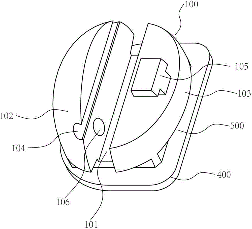
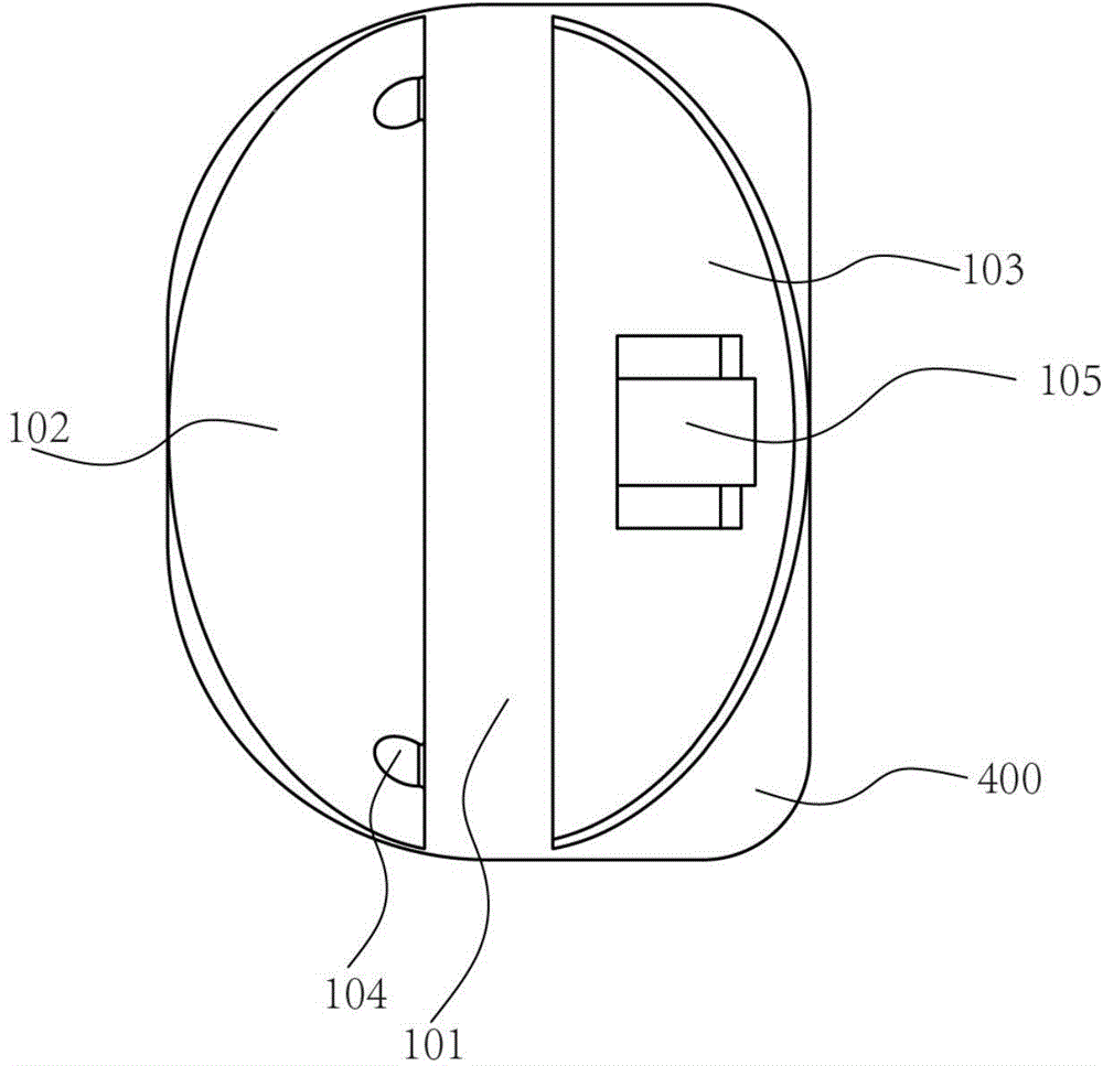
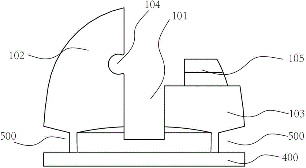
The invention discloses a traction bracket, an orthodontic system, and an orthodontic method thereof. The traction bracket includes a traction part, a main part, a cover part and a connection part. A main trough is formed in the main part. A locking traction hole is formed in the main part. One end of the locking traction hole is opened on surface of the main part to form a cylindrical traction part inlet while the other end is opened in the main trough in the main part to form a locking hole. The traction part is matched with and connected to the locking traction hole. The main part is connected to the cover part through the connection part. The bottom surface of the cover part is matched with the surface of the main part and covers the main trough. The surface of the cover part is matched with the surface of the main part to form a smooth curve surface. The traction part in the traction bracket is convenient to mount. The traction part not only helps the traction bracket to slide but also completes locking of the bracket and an arch wire after change of a traction bolt (a locking bolt) so as to achieve corresponding orthodontic effects.

Description

technical field [0001] The invention relates to the field of fixed orthodontic technology and tooth orthodontics, in particular to a traction bracket, an orthodontic orthodontic system and an orthodontic method. Background technique [0002] Bracket is an important part of fixed orthodontic technology, and it is an appliance for correcting deformity of tooth arrangement. The adhesive is directly bonded to the surface of the crown, and the arch wire passes through the bracket to exert various types of correction force on the tooth to achieve the purpose of orthodontic treatment. At present, the bracket ligation wing, the main groove, and the bottom plate are all integrated in the world. The arch wire for correction is fixed in the main groove, and the teeth and the bracket slide along the arch wire as a whole. However, the ratio of the length of the main groove of the current bracket to the whole bracket is small, which is not conducive to the fixation of the arch wire, and ...

Claims


Application Information

Patent Timeline
IPC IPC(8): A61C7/34
CPCA61C7/34A61C7/125A61C7/22A61C7/14A61C7/287A61C7/20
Inventor 吉利
Owner 吉利
Learn More