Unlock mechanism of optical fiber communication module

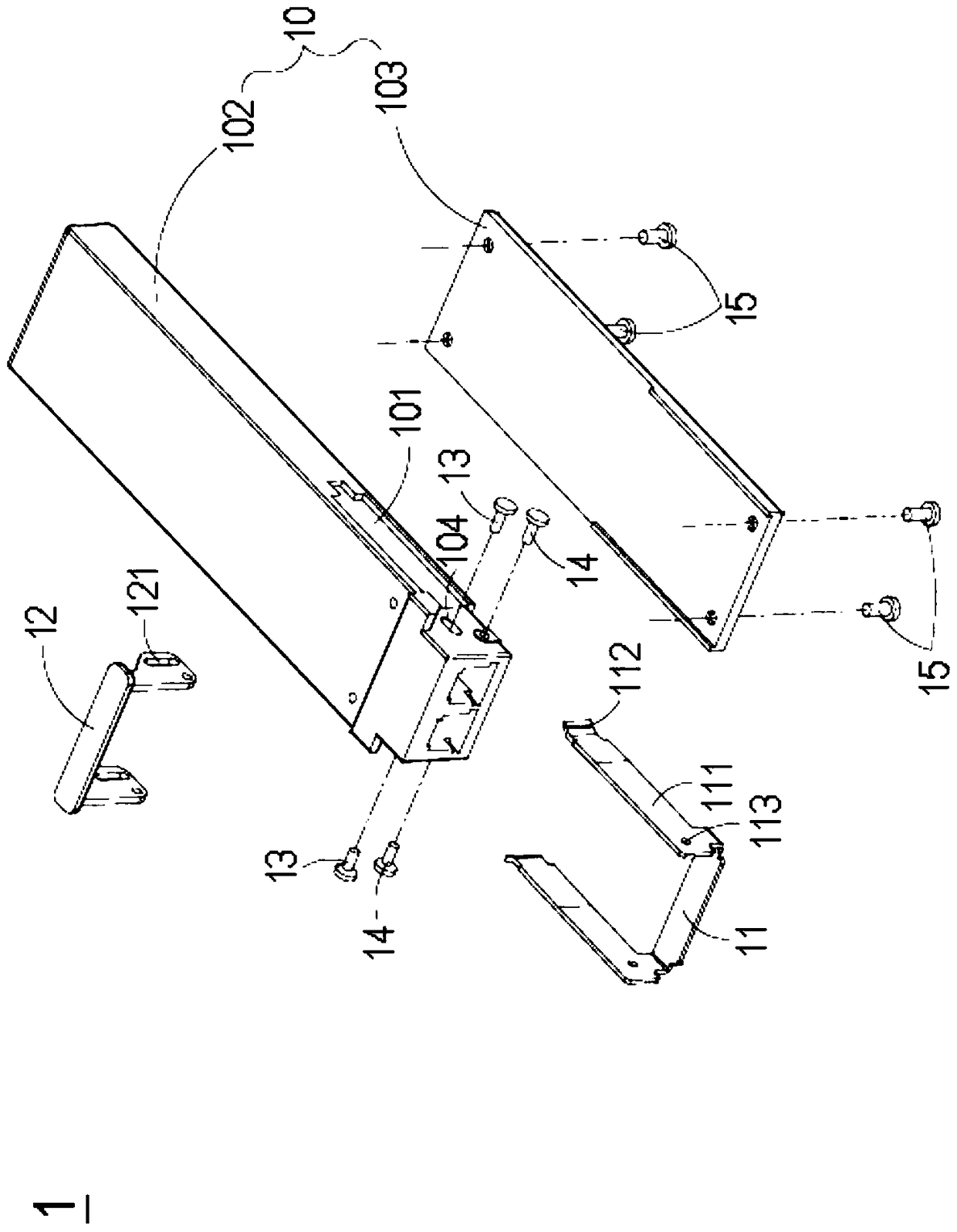
A technology of optical fiber communication and unlocking mechanism, applied in the direction of optical fiber transmission, electromagnetic transceiver, etc., can solve the problems of sliding arm 111 deformation, inconvenient use, complicated assembly and time-consuming

Active Publication Date: 2018-10-23
DELTA ELECTRONICS INC
View PDF3 Cites 0 Cited by
  • Summary
  • Abstract
  • Description
  • Claims
  • Application Information

AI Technical Summary

Problems solved by technology

It can be seen from this that the unlocking mechanism 1 of the conventional optical fiber communication module needs to align each component first, and then through multiple locking components such as the first locking component 13, the second locking component 14 and the third locking component 15, lock the The connection of components such as the body 10, the slider 11 and the handle 12 is quite complicated and time-consuming in assembly, and also increases the cost of component manufacturing and management, and each component is fixed by a rigid locking method, resulting in a small range of flexibility for the component
[0006] Furthermore, when the unlocking mechanism 1 of the optical fiber communication module is disengaged from the socket structure, the sliding arm 111 of the sliding member 11 is likely to be displaced due to excessive pulling force, causing the sliding arm 111 to deform or break away from the chute 101 , causing inconvenience in use

Method used


Image

  • Unlock mechanism of optical fiber communication module
  • Unlock mechanism of optical fiber communication module
  • Unlock mechanism of optical fiber communication module

Examples


Embodiment Construction

[0057] Some typical embodiments embodying the features and advantages of the present invention will be described in detail in the description in the following paragraphs. It should be understood that the present invention can have various changes in different aspects, all of which do not depart from the scope of the present invention, and the description and drawings therein are used as illustrations in nature rather than limiting the present invention .

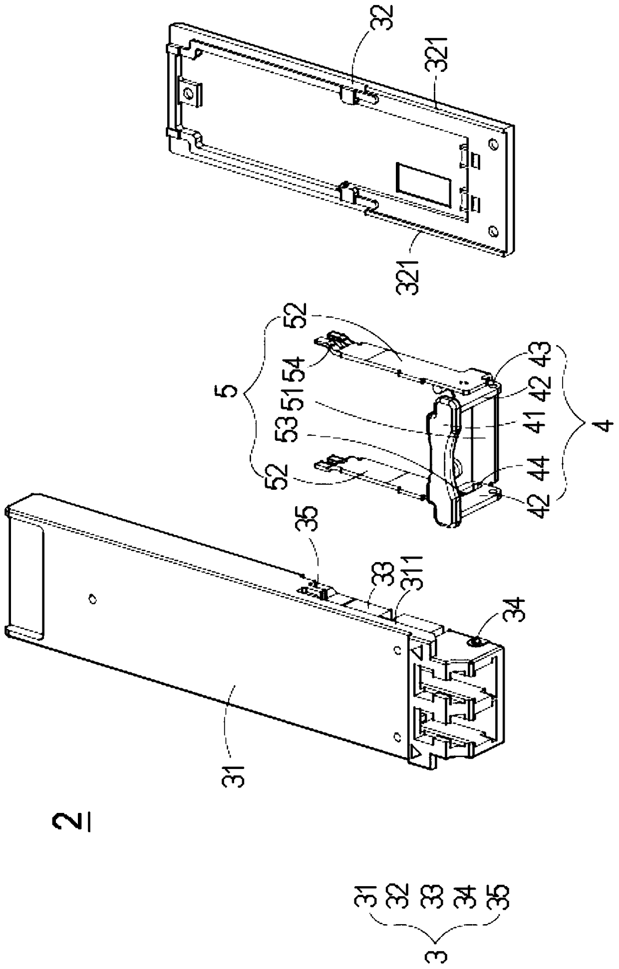
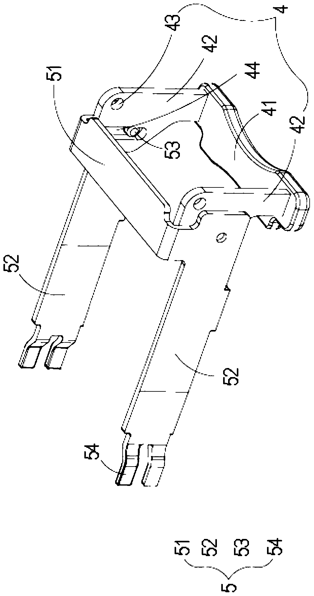
[0058] see figure 2 , which is an exploded schematic view of the unlocking mechanism of the optical fiber communication module in a preferred embodiment of the present invention. As shown in the figure, the unlocking mechanism 2 of the optical fiber communication module of the present invention is inserted into the socket structure 6 corresponding to the communication device (such as Image 6 shown), and at least includes a body 3 , a handle 4 and a sliding element 5 . Wherein, the main body 3 is respectively provided wit...


PUM


Abstract

The invention provides an unlocking mechanism of an optical fiber communication module. The unlocking mechanism of optical fiber communication module is inserted in a socket structure and at least comprises a body, a pull handle and a sliding element, wherein two opposite side surfaces of the body are respectively provided with a sliding groove. The pull handle is pivoted to the body and can be rotated to a clamping locking position and an unlocking position around an axis relative to the body, and two opposite sides of the pull handle are respectively provided with a first engaging guiding part. The sliding element is provided with two extending arms and two second engaging guiding parts, each second engaging guiding part is arranged on the corresponding extending arm, each extending arm is correspondingly arranged in the sliding groove of the body in a sliding manner, and each second engaging guiding part is correspondingly assembled with the first engaging guiding part of the pull handle. When the pull handle is rotated from the clamping clocking position to the unlocking position around the axis, the second engaging guiding parts of the sliding element are horizontally moved along the first engaging guiding parts of the pull handle so as to drive the extending arms to slide outwards along a straight line, so that the unlocking mechanism is separated from the socket structure.

Description

technical field [0001] The invention relates to an optical fiber communication module, in particular to an optical fiber communication module with an unlocking mechanism. Background technique [0002] With the rapid development of computer systems and related peripheral equipment in recent years, it is the trend of the times to increase the speed of information transmission to cope with the execution of highly complex tasks, such as digital signal transmission and image analysis. Under such demands, Optical fiber technology has emerged accordingly, which can be applied to long-distance or short-distance signal transmission, so as to use high-speed optical signals to replace known electrical signals to achieve the purpose of increasing the speed of information transmission. [0003] The optical fiber communication module is used as a signal transmission between electronic devices. Therefore, in order to increase the flexibility of the system design and facilitate maintenance,...

Claims


Application Information

Patent Timeline
Patent Type & Authority Patents(China)
IPC IPC(8): H04B10/25H04B10/40
Inventor 苏丽华
Owner DELTA ELECTRONICS INC
Why Eureka
Try Eureka