Feed clearing device of lathe

A technology for cleaning devices and lathes, which is applied in the direction of automatic/semi-automatic lathes, turning equipment, tool holder accessories, etc. It can solve problems such as uncleaned bars, low service life of lathes, and inability to eliminate the impact of impurities on the service life of lathes. Achieve the effect of prolonging the service life

Inactive Publication Date: 2016-10-12
苏州天朋精密元器件有限公司
View PDF7 Cites 1 Cited by
  • Summary
  • Abstract
  • Description
  • Claims
  • Application Information

AI Technical Summary

Problems solved by technology

However, during the entire machining process of the lathe machining shaft, there is no process of cleaning the bar. The impurities attached to the bar will enter the interior of the lathe along with the shaft. Even if the frequency of maintenance of the lathe is increased, the impact of impurities on the service life of the lathe cannot be eliminated. Therefore, the existing lathe has the defect of low service life

Method used


Image

  • Feed clearing device of lathe
  • Feed clearing device of lathe

Examples


Embodiment Construction

[0015] The specific implementation manners of the present invention will be further described in detail below in conjunction with the accompanying drawings and embodiments. The following examples are used to illustrate the present invention, but are not intended to limit the scope of the present invention.

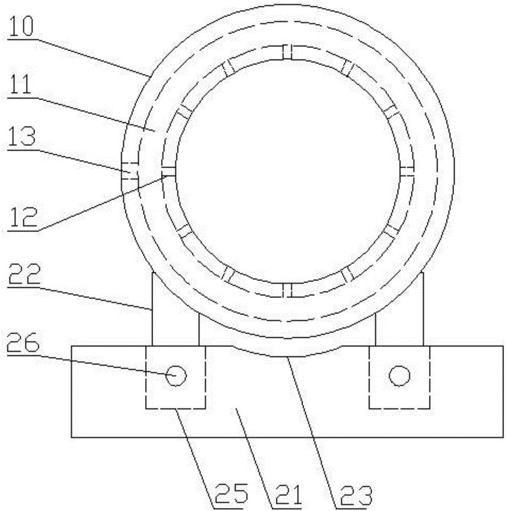
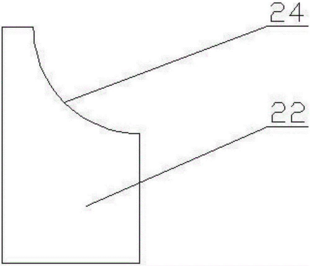
[0016] see figure 1 and figure 2 According to a preferred embodiment of the present invention, a lathe feeding and cleaning device includes a cylinder 10 with open ends, and two support mechanisms for supporting the two ends of the cylinder 10 respectively. The cylinder wall of the cylinder 10 is provided with There is an air duct 11 that is coaxial with the cylinder 10 and has a circular cross-section. The inner wall of the cylinder 10 is provided with several air outlet holes 12 communicating with the air duct 11. The outer wall of the cylinder 10 is provided with air ducts 11. Connected, used to connect to the air inlet 13 of the fan. In this way, when the bar passe...


PUM


Abstract

The invention relates to a feed clearing device of a lathe. The feed clearing device comprises a cylinder with two end openings and two support mechanisms separately supporting the two ends of the cylinder. An air pipeline which is coaxial with the cylinder and is provided with a round cross section is arranged in the cylinder wall of the cylinder, a plurality of air outlet holes communicating with the air pipeline are formed in the inner wall of the cylinder, and an air inlet which communicates with the air pipeline and is used for connecting a fan is arranged on the outer wall of the cylinder. According to the feed clearing device of the lathe, wind is blown towards the surface of a bar material from all directions of the inner wall of the cylinder, and impurities and dust which are attached to the surface of the bar material can be fully blown away. The feed clearing device ensures that no impurities enter the lathe, so that the service life of the lathe is prolonged.

Description

technical field [0001] The invention relates to a cleaning device, in particular to a material feeding and cleaning device for a lathe. Background technique [0002] Lathes, also known as machine tools, are mainly used to process shafts, disks, sleeves and other workpieces with rotating surfaces, mainly cylinders, and are the most widely used type of machine tools in machinery manufacturing and repair factories. When the lathe is machining the shaft, first the bar is placed on the feeding device, then the bar is sent into the lathe from the lathe inlet to process the bar through the turning tool, and finally the processed shaft is sent out through the arrangement mechanism . However, during the entire machining process of the lathe machining shaft, there is no process of cleaning the bar. The impurities attached to the bar will enter the interior of the lathe along with the shaft. Even if the frequency of maintenance of the lathe is increased, the impact of impurities on th...

Claims


Application Information

Patent Timeline
Patent Type & Authority Applications(China)
IPC IPC(8): B23B13/12
CPCB23B13/12B23B2270/28
Inventor 付朝
Owner 苏州天朋精密元器件有限公司
Why Eureka
Try Eureka