Downward blowing device of plastic hollow container of blowing machine

A blow molding machine and empty container technology, which is applied in the field of down blowing devices for plastic hollow containers, can solve problems such as many oil pipes, scrapped products, and oil leakage.

Active Publication Date: 2016-10-12
SUZHOU TONGDA MACHINERY
View PDF11 Cites 1 Cited by
  • Summary
  • Abstract
  • Description
  • Claims
  • Application Information

AI Technical Summary

Problems solved by technology

[0003] Chinese patent authorization announcement number CN202062631U recommends "three-layer plastic container forming machine", CN201941151U provides "plastic container full-automatic hollow forming machine" and CN202162995U introduces "large plastic container full-automatic hollow forming machine". The down-blowing device is mentioned, but the specific structure of the down-blowing device is not given, especially the structural inspiration of how to make the two blowing needle mechanisms of the structural system of the down-blowing device displace toward each other or in the opposite direction
[0006] The existing technology such as the aforementioned CN204894486U uses an oil motor (the patent is called "power motor") as the driving mechanism of the blowing needle. Because the control of the oil motor is difficult and t...

Method used


Image

  • Downward blowing device of plastic hollow container of blowing machine
  • Downward blowing device of plastic hollow container of blowing machine
  • Downward blowing device of plastic hollow container of blowing machine

Examples


Embodiment Construction

[0027] In order to understand the technical essence and beneficial effects of the present invention more clearly, the applicant will describe in detail the following examples, but the descriptions of the examples are not intended to limit the solutions of the present invention. Equivalent transformations that are only formal but not substantive should be regarded as the scope of the technical solution of the present invention.

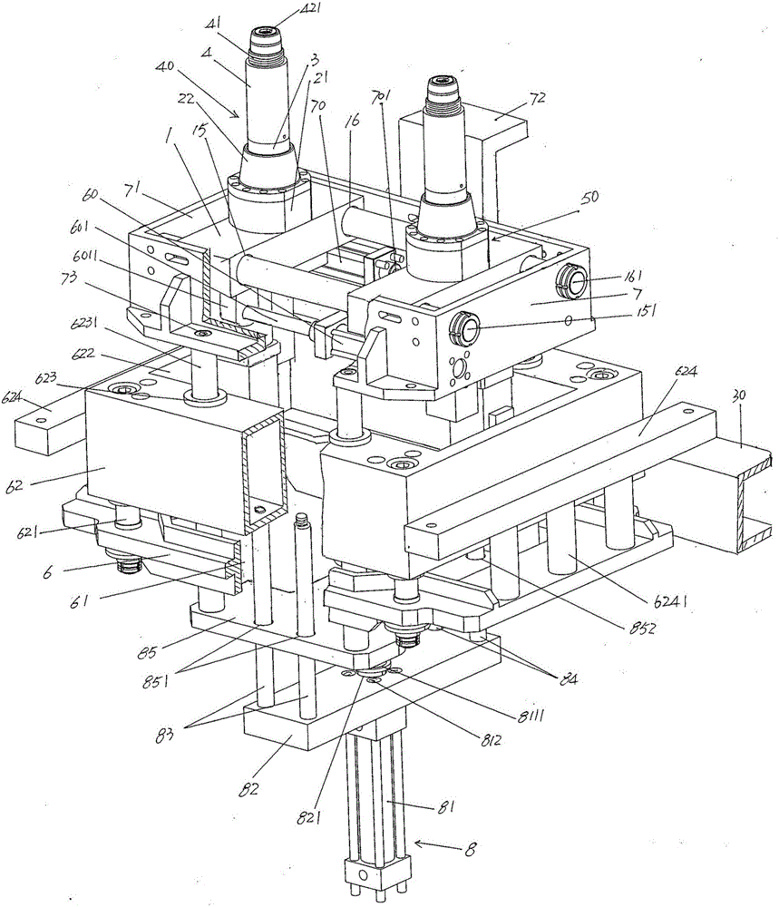
[0028] In the following descriptions, all concepts related to directionality or orientation of up, down, left, right, front and rear are defined in terms of figure 1 As far as the position and state of the present invention are concerned, it cannot be understood as a special limitation on the technical solution provided by the present invention.

[0029] See figure 1, shows a support seat 6 that is generally in the shape of a Chinese character, the support seat 6 forms a push plate lifting chamber 61, and the upper part of the support seat 6 passes th...


PUM


Abstract

The invention relates to a downward blowing device of a plastic hollow container of a blowing machine, and belongs to the technical field of hollow plastic product forming machines. The downward blowing device comprises a bearing base, a downward blowing base, a downward blowing base lifting drive mechanism, a first blowing needle mechanism, a right blowing needle mechanism, a first acting cylinder and a second acting cylinder. The bearing base is provided with a push plate lifting cavity, the upper portion of the bearing base is connected with a guiding sleeve base, and the guiding sleeve base is provided with a guiding sleeve base cavity. The downward blowing base is provided with a downward blowing base cavity, the lower portions of the front side and the rear side of the downward blowing base are connected with the tops of guide columns, and downward blowing base hitching legs are arranged at the middle portions of the front side and the rear side of the downward blowing base. The downward blowing base lifting drive mechanism is connected with the bottom of the guiding sleeve base and further fixed to the bottoms of the guide columns. The left blowing needle mechanism and the right blowing needle mechanism are arranged in the downward blowing base cavity. The first acting cylinder is arranged at the lower portion of the right side of the downward blowing base in a horizontal state, and a first acting cylinder column of the first acting cylinder faces the left blowing needle mechanism and is connected with the left blowing needle mechanism. The second acting cylinder is arranged at the lower portion of the left side of the downward blowing base in a horizontal state, and a second acting cylinder column faces the right blowing needle mechanism and is connected with the right blowing needle mechanism. The requirement for the material blank blow-up forming technology is met, the operation intensity is reduced, the blow-up forming efficiency is improved, and the situations of thread tooth rotting and collapsing are avoided.

Description

technical field [0001] The invention belongs to the technical field of hollow plastic product forming machinery, and in particular relates to a blowing device for a plastic hollow container of a blow molding machine. Background technique [0002] The plastic hollow containers mentioned above mainly refer to but are not absolutely limited to those with relatively large volume and two container openings, such as those used for filling pharmaceutical and chemical raw materials, oil products, various additives, additives and even hazardous chemicals. For double-port packaging barrels, the mold of the blow molding machine suitable for blowing such containers is usually composed of an upper sub-mold, a main mold and a lower sub-mold, and the structural system of the lower blowing device has the same two sets of blowing needle machines. [0003] Chinese patent authorization announcement number CN202062631U recommends "three-layer plastic container forming machine", CN201941151U pro...

Claims


Application Information

Patent Timeline
IPC IPC(8): B29C49/58B29C49/60B29C49/42
CPCB29C49/42B29C49/58B29C49/60
Inventor 刘俊吴国春陶艳冯强刘阳
Owner SUZHOU TONGDA MACHINERY
Why Eureka
Try Eureka