Box lowering mechanism

A technology for lowering and supporting boxes, applied to conveyors, conveyor objects, destacking of objects, etc., can solve problems such as inability to use a universal transmission mechanism, inability to accurately separate trays, and inability to accurately insert fork plates.

Active Publication Date: 2016-10-12
CHENGDU SOONTRUE MECHANICAL EQUIP CO LTD
View PDF6 Cites 13 Cited by
  • Summary
  • Abstract
  • Description
  • Claims
  • Application Information

AI Technical Summary

Problems solved by technology

[0005] In order to overcome the problem that the fork plate cannot be accurately inserted between the trays in the actual application of the existing box-down mechanism, resulting in the inability of the trays to be separated accurately, and the existing various box-down mechanisms cannot be used in common with the existing transmission mechanism. problem, now propose a lower box mechanism

Method used


Image

  • Box lowering mechanism
  • Box lowering mechanism
  • Box lowering mechanism

Examples


Embodiment 1

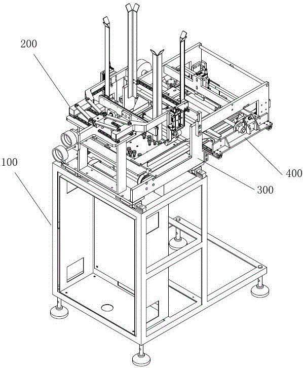
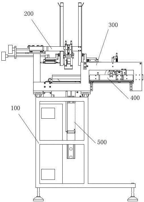
[0108]A lower box mechanism includes a support 100, a box loading frame, a tray conveying pusher 300 for pushing the tray horizontally, and a tray positioning pusher 400 for pushing the tray downward, and the bracket 100 is provided with In the box loading frame, one end of the tray delivery pushing part 300 is located below the box loading frame, the other end of the tray delivery pushing part 300 is located below the tray positioning pushing part 400, and the tray delivery pushing part 300 Located next to the box-loading frame, a lifting and absorbing component 500 for absorbing the tray is also arranged below the box-packing frame, and the lifting and absorbing component 500 is connected with the bracket 100 .

[0109] The tray is placed in the box loading frame, and the lowermost tray is absorbed by the lifting and absorbing part 500, and then falls onto the tray conveying pushing part 300, and then the tray conveying pushing part 300 translates and pushes the tray to the p...

Embodiment 2

[0122] A lower box mechanism includes a support 100, a box loading frame, a tray conveying pusher 300 for pushing the tray horizontally, and a tray positioning pusher 400 for pushing the tray downward, and the bracket 100 is provided with In the box loading frame, one end of the tray delivery pushing part 300 is located below the box loading frame, the other end of the tray delivery pushing part 300 is located below the tray positioning pushing part 400, and the tray delivery pushing part 300 Located next to the box-loading frame, a lifting and absorbing component 500 for absorbing the tray is also arranged below the box-packing frame, and the lifting and absorbing component 500 is connected with the bracket 100 .

[0123] The tray is placed in the box loading frame, and the lowermost tray is absorbed by the lifting and absorbing part 500, and then falls onto the tray conveying pushing part 300, and then the tray conveying pushing part 300 translates and pushes the tray to the ...

Embodiment 3

[0152] On the basis of the embodiment 1-2, the tray conveying pusher 300 includes a horizontal frame 301, the horizontal frame 301 is provided with a driving shaft 302, both ends of the main transmission shaft are connected with a timing belt 303, the The timing belt 303 is provided with a push rod 304 for horizontally pushing the tray, the bottom of the horizontal frame 301 is an open structure, the driving shaft 302 is connected with a first motor 305 to drive its rotation, the timing belt 303 The other end is provided with a driven shaft 306 , and both the driving shaft 302 and the driven shaft 306 are installed on the horizontal frame 301 . The bottom of the horizontal frame 301 is provided with an open structure. One is to make things easier for the tray when it falls on the tray conveying part. Subsequently, it can be pushed down from the tray conveying pushing part 300 to other stations. Theoretically, the driven shaft 302 can also be provided with the driven shaft 302...


PUM


Abstract

The invention relates to the fields of mechanical processing and box packing, in particular to a box lowering mechanism. The box lowering mechanism comprises a support, a box containing frame, a supporting box conveying and pushing component used for horizontally pushing supporting boxes, and a supporting box positioning and pushing component used for pushing the supporting boxes downwards. The box containing frame is arranged on the support. One end of the supporting box conveying and pushing component is located below the box containing frame. The other end of the supporting box conveying and pushing component is located below the supporting box positioning and pushing component. The supporting box conveying and pushing component is located beside the box containing frame. A lifting adsorption component used for adsorbing the supporting boxes is further arranged below the box containing frame. The lifting adsorption component is connected with the support. The supporting boxes are placed in the box containing frame. The lowermost supporting box falls onto the supporting box conveying and pushing component after being adsorbed by the lifting adsorption component, then the supporting box is horizontally pushed by the supporting box conveying and pushing component to the position below the supporting box positioning and pushing component, and then the supporting box positioning and pushing component pushes the supporting box downwards, so that the supporting box falls onto a subsequent conveying belt.

Description

technical field [0001] The invention relates to the field of mechanical processing box loading, in particular to a box unloading mechanism. Background technique [0002] In the existing field of mechanical processing and boxing, when the products to be boxed are processed, it is usually necessary to perform boxing operations, but the existing boxing is basically to put the food directly into the tray by hand, and stack The trays together often need to be placed manually so that the products can automatically fall into the trays. [0003] In view of the above situation, the applicant applied for the existing patent for improving the cartoning process. For example, the patent application number is CN201520254060.6, the application date is 2015.04.24, and the practical name is "the unloading mechanism of the food cartoning machine". The new type patent, its technical proposal is: the utility model relates to the field of food processing machinery and equipment, specifically, t...

Claims


Application Information

Patent Timeline
Patent Type & Authority Applications(China)
IPC IPC(8): B65B43/46B65B43/48B65G59/06B65G47/82B65G47/06
CPCB65B43/46B65B43/48B65G47/06B65G47/82B65G59/062B65G2201/025
Inventor 薛博勋彭涛
Owner CHENGDU SOONTRUE MECHANICAL EQUIP CO LTD
Why Eureka
Try Eureka